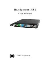
TiePie Handyscope HS5 series Скачать руководство пользователя страница 6

2

Chapter 1

Содержание Handyscope HS5 series

Страница 1: ...Handyscope HS5 User manual TiePie engineering...

Страница 2: ...t grounded power supplies A short circuit current will flow if the ground of the Handyscope HS5 is connected to a positive voltage This short circuit current can damage both the Handyscope HS5 and the...

Страница 3: ...tion utility 15 5 Hardware installation 21 5 1 Power the instrument 21 5 1 1 External power 21 5 2 Connect the instrument to the computer 22 5 2 1 Found New Hardware Wizard 22 5 3 Plug into a differen...

Страница 4: ...igger system 35 9 4 Arbitrary Waveform Generator 36 9 5 Power 39 9 6 Multi instrument synchronization 39 9 7 Physical 39 9 8 I O connectors 39 9 9 Interface 39 9 10 System requirements 40 9 11 Environ...

Страница 5: ...at voltages higher than 25 VAC or 60 VDC Do not operate the equipment in an explosive atmosphere or in the presence of flammable gases or fumes Do not use the equipment if it does not operate properl...

Страница 6: ...2 Chapter 1...

Страница 7: ...S Handyscope HS5 220 XM S XMS Handyscope HS5 110 XM S XMS Handyscope HS5 055 XM S XMS for which this declaration is valid is in compliance with EN 55011 2009 A1 2010 IEC 61000 6 1 EN 61000 6 1 2007 EN...

Страница 8: ...avoid release of such substances into the environment and to reduce the use of natural resources recycle the Handyscope HS5 in an appropriate system that will ensure that most of the materials are reu...

Страница 9: ...o channel measuring in strument with Arbitrary Waveform Generator The Handyscope HS5 is available in several models with different maximum sam pling frequencies 50 MS s 100 MS s 200 MS s or 500 MS s T...

Страница 10: ...MiS 32 MiS Table 3 3 Maximum record lengths per channel Optionally available for the Handyscope HS5 are SureConnect connection test and resistance measurement SureConnect connec tion test tells you im...

Страница 11: ...se intervals the size of the input signal is converted to a number The accuracy of this number depends on the resolution of the instrument The higher the resolution the smaller the voltage steps in wh...

Страница 12: ...visible in figure 3 3 with a higher sampling frequency the original signal can be reconstructed much better from the measured samples Figure 3 3 The effect of the sampling frequency The sampling freq...

Страница 13: ...000 1000 1250 250 1000 1250 2250 0 0 1250 1250 0 1250 1250 1000 1000 1250 2250 1000 1250 250 2000 2000 1250 3250 2000 1250 750 Table 3 4 Aliasing As stated before when sampling a signal only frequenci...

Страница 14: ...l appears to be 4 ms which corresponds to an apparent frequency alias of 250 Hz 1 25 kHz 1 kHz To avoid aliasing always start measuring at the highest sam pling frequency and lower the sampling freque...

Страница 15: ...refore the full range is 400 mV This results in a smallest detectable voltage step of 0 400V 16384 24 41 V 3 4 Signal coupling The Handyscope HS5 has two different settings for the signal cou pling AC...

Страница 16: ...attenuation is achieved by means of an attenuation network This attenuation network has to be adjusted to the oscil loscope input circuitry to guarantee frequency independency This is called the low f...

Страница 17: ...Figure 3 6 correct Figure 3 7 under compensated Figure 3 8 over compensated Introduction 13...

Страница 18: ...14 Chapter 3...

Страница 19: ...pre installed by the driver setup program This makes sure that all required files are located where Windows can find them When the instrument is plugged in Windows will detect new hardware and instal...

Страница 20: ...gure 4 1 Driver install step 1 When drivers were already installed the install utility will re move them before installing the new driver To remove the old driver successfully it is essential that the...

Страница 21: ...t should now be disconnected Then the removal of the existing driver can be continued by clicking Next Clicking Yes will ignore the fact that the instrument is still connected and continue removal of...

Страница 22: ...stallation may inform about the drivers not being Windows Logo Tested The driver is not causing any danger for your system and can be safely installed Please ignore this warning and continue the insta...

Страница 23: ...the drivers Clicking Install will remove existing drivers and install the new driver A remove entry for the new driver is added to the software applet in the Windows control panel Figure 4 6 Driver in...

Страница 24: ...20 Chapter 4...

Страница 25: ...B ports have a maximum limit for both the inrush current peak and the nominal current When either of them is exceeded the USB port will be switched off As a result the connection to the Handyscope HS5...

Страница 26: ...ardware Wizard will appear Depending on the Windows version the New Hardware Wizard will show a number of screens in which it will ask for information regarding the drivers of the newly found hardware...

Страница 27: ...rdware and will ask to install the drivers again This is controlled by Microsoft Windows and is not caused by TiePie engineering 5 4 Operating conditions The Handyscope HS5 is ready for use as soon as...

Страница 28: ...24 Chapter 5...

Страница 29: ...d shared trigger signals Figure 6 1 Auxilary I O connectors Connecting is done by daisy chaining the auxiliary I O con nectors of the instruments prior to starting the software using a special couplin...

Страница 30: ...26 Chapter 6...

Страница 31: ...to a potential other than ground will result in a short circuit that may damage the device under test the Handy scope HS5 and the computer 7 2 AWG output connector The AWG BNC connector is the output...

Страница 32: ...28 Chapter 7...

Страница 33: ...f the 9 pin D sub extension connector The specifications of the dedicated power connector are Pin Dimension Description Center pin 1 3 mm positive Outside bushing 3 5 mm ground Figure 8 2 Power connec...

Страница 34: ...an be connected to the dedicated power connector Figure 8 3 Power adapter 8 1 2 USB power cable A special USB external power cable is supplied with the Handy scope HS5 that can be used instead of a po...

Страница 35: ...Power IN 3 EXT 3 LVTTL 8 Power OUT see description 4 I2C SDA 9 reserved 5 I2C SCL Table 8 2 Pin description Extension connector Pins EXT 1 EXT 2 and EXT 3 are equipped with internal 1 kOhm pull up res...

Страница 36: ...connector Pin Description Pin Description 1 GND 11 Data OK P EXT LVDS 2 EXT CLK P LVDS 12 Data OK N EXT LVDS 3 EXT CLK N LVDS 13 reserved 4 GND 14 Generator Trigger I O 5 Data OK I O 15 reserved 6 re...

Страница 37: ...5 pF Maximum voltage 200 V DC AC peak 10 kHz Maximum voltage 1 10 probe 600 V DC AC peak 10 kHz Bandwidth 3dB at 75 of full scale input Ch1 250 MHz Ch2 100 MHz AC coupling cut off freq 3dB 1 5 Hz Sure...

Страница 38: ...omputers the highest streaming rates may not be available due to computer restrictions Model 540 Model 530 8 bit measuring one channel 40 MS s 8 bit measuring two channels 20 MS s 12 14 bit measuring...

Страница 39: ...annels 1 sample resolution Trigger hold off 0 to 64 MSamples 1 sample resolution Trigger delay 0 to 16 GSamples 1 sample resolution Segmented trigger Available via LibTiePie SDK Maximum number of segm...

Страница 40: ...overload is applied Instrument will tolerate a short circuit to ground indefinitely System Constant Data Size Memory Standard model 256 KiSamples XM option 64 MiSamples Operating modes Continuous trig...

Страница 41: ...epending on model Model 540 1 Hz to 40 MHz above 30 MHz not specified Model 530 1 Hz to 30 MHz Model 220 1 Hz to 20 MHz Model 110 1 Hz to 10 MHz Model 055 1 Hz to 5 MHz Rise fall time 8 ns Overshoot 1...

Страница 42: ...ry Count 1 to 65535 Trigger Software external Sweep Available only on models with extended memory option XM Waveforms Sine square triangle noise arbitrary Type Linear logarithmic Count Up down Trigger...

Страница 43: ...ion Maximum number of instruments Limited by available number of USB ports Synchronization accuracy 0 ppm 9 7 Physical Height 25 mm 1 0 Length 170 mm 6 7 Width 140 mm 5 2 Weight 430 g 15 ounce USB cor...

Страница 44: ...55 C Relative humidity 10 to 90 non condensing Storage Ambient temperature 20 C to 70 C Relative humidity 5 to 95 non condensing 9 12 Certifications and Compliances CE mark compliance Yes RoHS Yes EN...

Страница 45: ...1 10 17 pF Compensation range 1 1 1 10 10 to 35 pF Working voltage 1 1 300 V CAT I 150 V CAT II DC peak AC 1 10 600 V CAT I 300 V CAT II DC peak AC 9 14 Package contents Instrument Handyscope HS5 Pro...

Страница 46: ...42 Chapter 9...

Страница 47: ...uggestions and or remarks regarding this manual please contact TiePie engineering Koperslagersstraaat 37 8601 WL SNEEK The Netherlands Tel 31 515 415 416 Fax 31 515 418 819 E mail support tiepie nl Si...

Отзывы: