

TSol01
CENTRALINA per PANNELLI SOLARI a
CIRCOLAZIONE NATURALE
CONTROLLER for NATURAL
CIRCULATION SOLAR PANEL
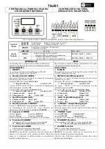
fig.1. Aspetto esterno e schema di collegamento/ Exterior Aspect and wiring diagram
Sonda S1
Probe S1
Sonda Boyler:
Range di Temperatura 0 – 100 °C
Boiler Probe:
Temperature range 0 – 100 °C
Ingressi
Inputs
CRONO
Contatto per Accensione / Spegnimento
Contact for ON/OFF
LINE OUT
230 Vac
3(N) - 4(F)
INTEG.
Integrazione:
Integration:
Contatti in scambio
Free Contacts on commutation
5(COM) - 6(N.C.) - 7(N.O.)
Uscite
Outputs
AUX
Ausiliario:
Auxiliary:
Contatti in scambio
Free Contacts on commutation
8(COM) - 9(N.C.) - 10(N.O.)
GENERALITÀ
MAIN
La centralina (fig.1) è studiata per la gestione automatica di
impianti con pannello solare termico a circolazione naturale
The controller is studied to manage automatically the system
with natural circulation thermic panels
FUNZIONAMENTO
FUNCTIONING
1.
ON/OFF
La pressione prolungata del tasto P4 porta in ON/OFF
La spia ‘OFF’ segnala stato di SPENTO
1.
ON/OFF
The prolonged pressure of the button P4 switch ON/OFF The
led ‘OFF’ signals the OFF state
2.
Gestione Uscita ‘INTEG.’
Tale uscita è dedicata al controllo di un sistema di integrazione
del tipo resistenza elettrica o altro
Il pulsante‘P3’attiva il modo MANUALE:
♦
Modo MANUALE:
led MAN ‘ON’
L’uscita ‘INTEG’ risulta ATTIVA e si disattiva al superamento
della temperatura massima A05
Il pulsante‘P2’attiva il modo AUTOMATICO:
♦
Modo AUTOMATICO:
led AUTO ‘ON’
S1 minore di A01
Uscita ‘ON’
S1 maggiore di
A01
Uscita ‘OFF’
2.
INTEG. Output Management
This output is to control an integration device like the electric
resistance one or others
The button ‘P3’ activates the Manual/Automatic Mode.
♦
MANUAL Mode:
led MAN ‘ON’
The output ‘INTEG’ is ON and is deactivated over the
maximum temperature A05
The button ‘P2’ activates the AUTOMATIC Mode.
♦
AUTOMATIC Mode:
led AUTO ‘ON’
S1 under A01
Output ‘ON’
S1 over A01
Output ‘OFF’
3.
Gestione Uscita ‘AUX.’
S1 minore di A02
Uscita ‘OFF’
S1 maggiore di
A02
Uscita ‘ON’
3. ‘
AUX.’ Output Management
S1 under A02
Output ‘OFF’
S1 over A02
Output ‘ON’
4. Gestione Uscita ‘LINE OUT’
L’uscita è ATTIVA nel caso di dispositivo ACCESO:
La alimentazione sui morsetti può essere utilizzata per
alimentare carichi locali entro la portata del FUSIBILE
4. ‘
LINE OUT’ Output Management
The output is ON when the controller is ON:
The power supply can be used to supply local loads within the
range of the FUSE
5. Ingresso ‘CRONO’
Contatto Aperto:
dispositivo SPENTO
Contatto Chiuso:
dispositivo ACCESO
In caso di non utilizzo lasciare i terminali 15 e 16 scollegati.
5.
‘CRONO’ Input
Contact OPENED:
Controller OFF
Contact CLOSED:
Controller ON
If you don’t use, connectors 15 and 16 opened.
6. Funzione STANDBY
Se dispositivo OFF, se S1 supera il termostato A11
Il dispositivo automaticamente va in ON
6.
STANDBY Function
If the controller is OFF if S1 is over the thermostat A11
The controller goes automatically ON
7. Funzione ALLARME
Se S1 supera il termostato di allarme A11
Viene attivata la segnalazione di acustica e visiva
SILENCE: la segnalazione acustica può essere disattivata per 5
minuti con la pressione di un pulsante qualsiasi. Dopo tale
tempo, se la condizione di allarme permane, la segnalazione
acustica si riattiva di nuovo.
7.
ALARM Function
If S1 is over the alarm thermostat A11
An acoustic and visual signal is activated
SILENCE: the acoustic signal can be deactivated for 5
minutes through the pressure of any button.
After this time, if the alarm condition continues, the acoustic
signal it is activated again.
1 2 3 4 5 6 7 8 9 10
AUX
P1
P2
P3
P4
INTEG.
13 14 15 16


