Synergy Controller Technical Manual, Revision H
Page 144
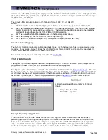
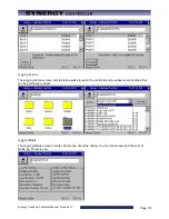
Information on the Selected Output is displayed in the text box at the bottom of the screen. Highlight an item
(Fan, HiAl, PIDH…) by pressing the output label and view the selected output properties below: for example
“1: B12a, Out 1, On/Off, On”
The output information is displayed in the following format: “A1 : A2, A3, A4, A5”
Where:
♦
A1: The location of the output as displayed on the screen 1-31 moving up to down, left to right.
♦
A2: The output board the device is connected to. The boards are referred to as 12a for the 12 output
board, 6a and 6b for sequential 6 output boards. The terms 12a, 6a, 6b correspond to the traditional
method of labeling these boards 1SM, 2SM and 3SM, respectively.
♦
A3: The output the highlighted device uses on the board specified above.
♦
A4: The output type, such as On/Off or Time Proportioning.
♦
A5: The current state of the output: On, Off or percent output (for example: 22%)
Chamber Output Mapping
The Synergy Controller supports multiple chambers types. Each chamber type has q unique device output
mapping. For example, Output 1 drives the chamber fan on Temp-Humidity and Temp-Only chambers. In
Temp-Temp chambers Output 10 drives the fan device.
The output maps for each chamber type are listed in
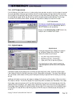
11.4 Digital Inputs
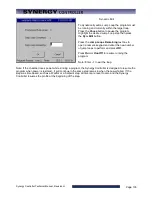
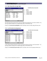
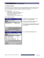
The Digital Input Screen displays the status of inputs from up to 16 switch closures. Waitfor steps can be
programmed to wait for a digital input state before it continues the program.
The Digital Inputs are located on connectors P1 and P3 on the Olympic board.
. Pin 1 on
P1 is ground. Pins 3 – 12 correspond to Digital Inputs 1 to 10. Digital Input 9 (Pin 11) is a TempGard Alarm
on chambers that have a TempGard alarm. If the chamber does not have a TempGard alarm, Input 9 must
be shorted to ground (pin 1). Use the Olympic Board Diagram in
Digital Inputs
LEDs show status of the controller’s 16 Digital
Inputs.
♦
Grey LED: Input Off
♦
Red LED: Input On
Example Digital Input Application
To turn on a test device in the middle of a test, the test engineer wants to wait for the device to finish
powering up before continuing with the program. To achieve this, he uses both Events and Digital Inputs.
First he uses Event 1 to drive the test unit power supply. Next he waits for the Digital Input 1 to signal the
unit under test to continue the program. The advantage of the Waitfor in this application is that it doesn’t
matter how long the startup process takes, it could take 1, 5 or 10 minutes or be different each time.
Содержание Synergy Compact
Страница 14: ...Synergy Controller Technical Manual Revision H Page 14 2 0 SPECIFICATIONS 2 1 Data Sheet...
Страница 71: ...Synergy Controller Technical Manual Revision H Page 71...
Страница 106: ...Synergy Controller Technical Manual Revision H Page 106...
Страница 123: ...Synergy Controller Technical Manual Revision H Page 123...
Страница 141: ...Synergy Controller Technical Manual Revision H Page 141 TE1151 6 Triac Output Board Schematic...
Страница 142: ...Synergy Controller Technical Manual Revision H Page 142 TE1708 6 Relay Board Schematic...
Страница 188: ...Synergy Controller Technical Manual Revision H Page 188...
Страница 274: ...Synergy Controller Technical Manual Revision H Page 274 Synergy Controller Step Syntax...
Страница 294: ...Synergy Controller Technical Manual Revision H Page 294...
Страница 312: ...Synergy Controller Technical Manual Revision H Page 312...
Страница 345: ...Synergy Controller Technical Manual Revision H Page 345...
Страница 346: ...Synergy Controller Technical Manual Revision H Page 346...

