12
CANOPY/FUELTANK/MOTOR MOUNT
❏
Cut away the excess plastic from each wheel pant half. Trial fit the
halves together and trim as needed. Use thick CA to join the halves at
the overlap and let cure.
❏
Drill two
5
⁄
16
” holes on either side of the pants where marked.
❏
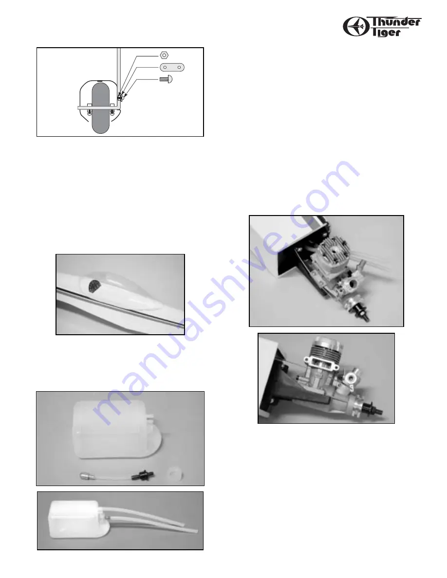
Slip the wheel pant onto the landing gear and at the same time
install the wheel and and wheel collar on either side. The landing gear
strut will extend beyond the outside of the wheel pant.
❏
Secure the pants with a metal landing gear strap and 2mm X 8mm
bolts and nuts. Pre-drill
3
⁄
32
” holes.
VIII. Canopy
❏
Install the instrument panel, and if desired, a pilot figure in the cockpit.
Trim the canopy to fit on top of the cockpit. Glue into place using RC-
56 canopy glue or equivalent. Locate the canopy trim tape to give the
canopy a finished look and a good seal.
IX. Fuel Tank
❏
Assemble the fuel tank by first cutting the silicone tube to 2-
1
⁄
2
" in
length. Press the straight plastic nipple (the 90˚ nipple is not used in
this plane) into the rubber stopper (saliva will ease insertion.) Now
slip the silicone tubing onto the nipple and insert the metal clunk into
the other end of the tubing. Insert this assembly into the tank clunk-
first and securely tighten the threaded cap on to hold everything
together.
❏
Attach a 6” piece of standard fuel line (not furnished) to both the
fuel outlet nipple and the vent nipple on the tank. The vent nipple is
the top one with the hole.
❏
Slide the fuel tank cap end-first) into the front of the fuselage,
threading the fuel lines through the oblong hole in the firewall.
The tubing coming from the tank’s fuel outlet (center) goes to the carb
and the tubing from the vent (upper) goes to the muffler’s pressure fit-
ting. Trim the length as needed. Wedge some pieces of foam rubber
or “bubble wrap” (not furnished) beside and on top of the tank to
gently hold it in place.
X. Motor Mount
❏
Install the motor mount using the four 3mm x 18mm screws.
❏
Set your engine on the motor mount. We have chosen the Thunder
Tiger Pro-46, which will provide plenty of power for aerobatics and
general flying.
❏
With your engine on the mount, you will need to measure 4
1
⁄
2
” from
the firewall to the front of the drive of the engine.
❏
Mark the engine mounting lug holes. Use a
7
⁄
64
drill bit to drill the
holes for the engine. Now install the engine using the four 3mm x
15mm self-tapping screws.
❏
With the engine mounted in place, find the throttle push rod wire
and make a Z-bend at one end. Install and attach the Z-bend end to the
engine as shown in the picture.


