THORLABS OTKBFM-CAL Скачать руководство пользователя страница 14

Calibration & Measurement Module for OTKB/OTKBFM


Chapter 5: Operation


TTN030035-D02


Page 

12   

5.2. Stiffness 

Calibration 

The OTKBFM-CAL software provides two stiffness calibration methods, the so-called PSD Roll-Off and 
Equipartition calibration.  The first approach uses the fact that the thermal motion of a spherical bead of known 
size suspended in water is well characterized. As the laser power is increased, the Brownian motion of the bead 
is constrained more and more by the increasing trap force restoring the bead to the center of the trap. A 
frequency analysis of the particle position can therefore be used to extract the stiffness parameter. The second 
approach is based on the equipartition theorem, which relates the energy of the particle to the temperature at 
which the experiment is conducted. Both methods are applied to the data collected from the detector during a 
force calibration allowing the user to verify the result. 

1.  Find a free bead and trap it. 
2.  Use the data recording tool to verify that the X and Y voltages of the quadrant detector are close to zero. If 

this is not the case then adjust the detector to minimize the voltages. 

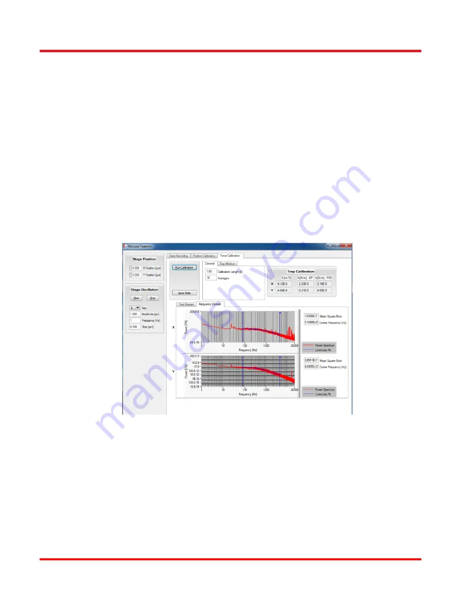
3.  Select the “Force Calibration” tab and run the calibration. Depending on the calibration length and the number 

of averages which are set, this measurement can take several seconds. The Fourier Transform of the data is 
displayed and you can click on the graph to set the lower/upper limit for the fit routine. Each time you change 
a limit, the fit is automatically recalculated and the stiffness determined. 

4.  It is possible to adjust the scale of the plots by holding down the CTRL key and clicking the left mouse button 

on the graph to draw a rectangle which defines the new range. In order to zoom out again, hold the CTRL key 
and press the right mouse button on the graph surface. 


Figure 9 

Example PSD Curve Acquired During Force Calibration 


Содержание OTKBFM-CAL

Страница 1: ...OTKBFM CAL Calibration and Measurement Module for OTKB with OTKBFM User Guide...

Страница 2: ...5 3 2 2 PSD Roll Off Method 5 Chapter 4 Setup 6 Chapter 5 Operation 10 5 1 Position Calibration 10 5 2 Stiffness Calibration 12 5 3 Sample Preparation 13 5 4 Saving Data 13 Chapter 6 Frequently Asked...

Страница 3: ...vice Symbol Description Direct Current Alternating Current Both Direct and Alternating Current Earth Ground Terminal Protective Conductor Terminal Frame or Chassis Terminal Equipotentiality On Supply...

Страница 4: ...trical shock CAUTION Caution is given when there is a possibility of damage to the product WARNING Given when there is danger of injury to users 2 2 General Warnings WARNING If the product is used in...

Страница 5: ...pproaches the most common technique is based on back focal plane detection As the laser beam passes through the sample plane interference occurs between the light which is transmitted through the trap...

Страница 6: ...cation of the trap while recording the detector voltage Using the sample stage steps of known size are used which then allow plotting of the position signal in volts versus the position signal in micr...

Страница 7: ...should be noted that for this approach it is necessary to first determine the position calibration for the detector 3 2 2 PSD Roll Off Method While the Roll Off method also makes use of the Brownian...

Страница 8: ...inistrative user rights for the installation 2 The Thorlabs APT software should already have been installed on your PC during the installation of the OTKBFM force module If not please download the APT...

Страница 9: ...lect Settings in one of the piezo controller windows and adjust the settings as shown in Figure 4 Close the window and do the same for the second piezo controller 7 Click Zero on the strain gauge read...

Страница 10: ...WARNING If the Piezo Driver is switched to closed loop mode without a feedback signal applied the piezo drive voltage will ramp up to the maximum limit If the limit is set to 75 V a protective circuit...

Страница 11: ...automatically added to your PC if it was not present already Start the NI MAX tool typically a link is found in your windows All Program list Right click on the NI USB 6212 device and rename it to OTK...

Страница 12: ...traints with the coverslip will restrict the Brownian motion while at heights above 5 m the optical trap loses its tight focus We assume that you have setup your tweezers system and aligned the detect...

Страница 13: ...trap position until you see a significant change in the voltage signals during the state oscillation Hint The stuck bead is aligned with the optical trap center when the voltage signal changes most s...

Страница 14: ...cted from the detector during a force calibration allowing the user to verify the result 1 Find a free bead and trap it 2 Use the data recording tool to verify that the X and Y voltages of the quadran...

Страница 15: ...one sphere for the duration of a measurement 5 4 Saving Data If the Stream to Disk flag is set on the Data Tracking screen a set of files will be saved Files can be named automatically using a time s...

Страница 16: ...ower cycle the K cube hub Then identify the K cube piezo and strain gauge controller pairs connected to the X and Y axis on the stage Set the piezo cubes to Open Loop temporarily and adjust the piezo...

Страница 17: ...OTKBFM CAL module d Check the PSD K Cube is set to Monitor Mode as shown in Fig 4 Use the Thorlabs APT User software to access the panel shown and adjust this setting 5 When I start data tracking in...

Страница 18: ...male XY Detector Signal Inputs 10 to 10 V SUM Detector Input 0 to 10 V XSG YSG Strain Gauge Inputs 0 to 10 V DAC Resolution 16 bit Sampling Range 400 kS s channel Outputs DAQ Manufacturer and Item Num...

Страница 19: ...Calibration Measurement Module for OTKB OTKBFM Chapter 8 CE compliance Page 17 Rev C August 2 2018 Chapter 8 CE compliance...

Страница 20: ...ther Thorlabs products such as Pure OEM products that means assemblies to be built into a unit by the user e g OEM laser driver cards Components Mechanics and optics Left over parts of units disassemb...

Страница 21: ...ww thorlabs de Email europe thorlabs com Scandinavia Thorlabs Sweden AB Bergfotsgatan 7 431 35 M lndal Sweden Tel 46 31 733 30 00 Fax 46 31 703 40 45 www thorlabs com Email scandinavia thorlabs com Fr...

Страница 22: ...www thorlabs com...

Отзывы: