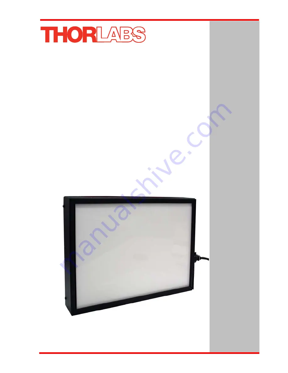
LSS10LED Lightbox for Laser Safety Signs
User Guide
Original Instructions
Страница 1: ...LSS10 LED Lightbox for Laser Safety Signs User Guide Original Instructions...
Страница 2: ...1 Control and Connection Overview 8 4 2 Using the Safety Interlock 9 4 3 Replacing the Internal Fuses 10 4 4 Inserting a Laser Safety Sign 10 4 5 Disabling the Brightness Control 11 4 6 Cleaning 11 C...
Страница 3: ...2 that prevent the use of interlock equipped laser systems unless the safety light is turned on The external interlock socket accepts a 2 5 mm phono jack supplied The lightbox is permanently fixed to...
Страница 4: ...rom electrical shock Warning Given when there is a risk of injury to users Caution Given when there is a risk of damage to the product Note Clarification of an instruction or additional information Wa...
Страница 5: ...nd can cause serious injury Appropriate care should be taken when using this device Persons using the device must understand the hazards associated with using high voltages and the steps necessary to...
Страница 6: ...s If you are uncertain contact a specialised installer Note The default configuration and labelling is for right handed use however the mounting holes allow the unit to be mounted for left hand use Ca...
Страница 7: ...unit should be hard wired only when it is permanently attached to the wall Only use 3 core 0 75 to 1 5 mm2 218 318 cable to EN 50525 2 11 to hard wire the unit Grommets with a flammability rating of U...
Страница 8: ...on is disconnected at the next step Fig 3 2 Removing the front panel 4 Unclip the connection to the LED circuit CON4 see Fig 3 3 then remove the panel 5 Ensure mains power is disconnected then move th...
Страница 9: ...Fig 3 4 Fig 3 4 Cable knock outs and strain relief clamp locations 7 If using an internal safety interlock perform the procedure detailed in Section 4 2 8 Re connect the LED circuit at CON4 9 Refit th...
Страница 10: ...rols overview BRIGHTNESS Used to control the light intensity of the lightbox when the external controls see Section 4 5 are enabled INTLK For use in laser safety applications see Section 4 2 POWER Use...
Страница 11: ...ceed 34V DC AC 0 5A and should be electrically isolated from hazardous circuits with reinforced insulation External connection is achieved via the jack socket on the right hand control panel see Fig 4...
Страница 12: ...be replaced as follows 1 Remove power from the unit 2 Remove the front panel see Fig 3 2 3 Locate the broken fuse see Fig 3 3 4 Replace the fuse with another of the same type 0 63A T 250 VAC 5 Refit t...
Страница 13: ...ternal control is bypassed and brightness is set internally 1 Isolate the unit from mains power 2 Remove the front Panel see Fig 3 2 3 Move switch SW3 to the INT position as shown below Warning The in...
Страница 14: ...ghtly dampened with water or a mild detergent Note The MIN setting corresponds to the brightness level set to minimum using the control panel pot Similarly the MAX setting corresponds to the max brigh...
Страница 15: ...wer 8W Minimum Brightness to 15 W Max Brightness Internal Fuses Qty 2 0 63A T 250 VAC Operating Temperature Range 5 to 40 C Dimensions W x D x H 362 0 x 257 x 50 mm 14 25 x 10 12 x 1 97 Weight 3 3 Kg...
Страница 16: ...harmful interference when the equipment is operated in a commercial environment This equipment generates uses and can radiate radio frequency energy and if not installed and used in accordance with th...
Страница 17: ...Rev A Nov 2017 Page 15 Chapter 6 Regulatory 6 2 CE Certificate...
Страница 18: ...il sales thorlabs com Support techsupport thorlabs com Europe Thorlabs GmbH Hans B ckler Str 6 85221 Dachau Munich Germany Tel 49 0 8131 5956 0 Fax 49 0 8131 5956 99 www thorlabs de Email europe thorl...
Страница 19: ...www thorlabs com...