


Thorlabs.com - Noise Eaters / Laser Amplitude Stabilizers
https://www.thorlabs.com/newgrouppage9_pf.cfm?guide=10&category_id=95&objectgroup_id=6107[7/7/2016 8:29:39 AM]
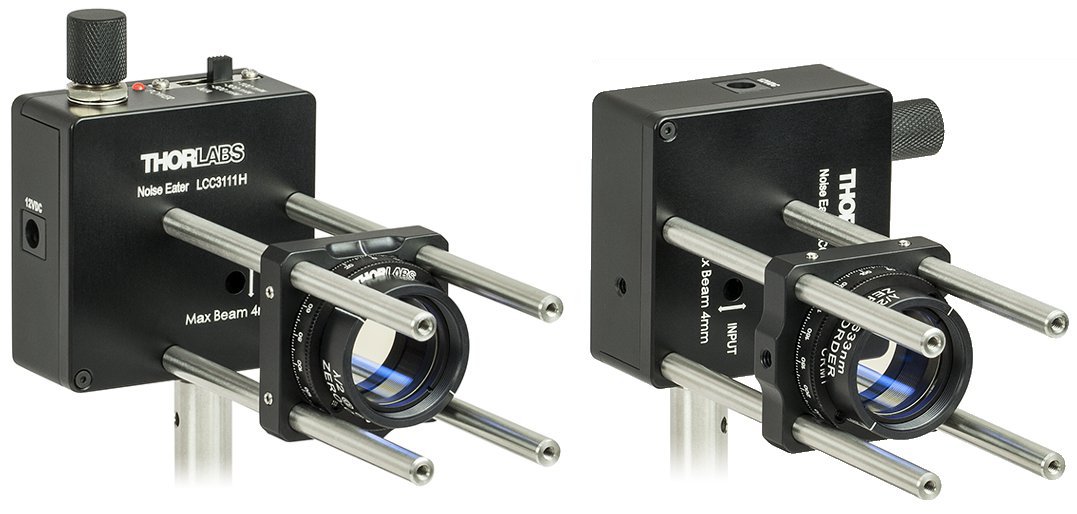
The Noise Eater can be post mounted in two different orientations to
match the input light's direction of polarization. A CRM1 Cage
Rotation Mount and four ER2 Cage Rods can mount a half-wave plate
for fine tuning the polarization alignment.
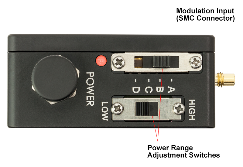
SMC Modulation Input
Jack
Top View Showing Power Range Adjustment
Switches
Thorlabs’ Liquid Crystal Noise Eater is a precision instrument for stabilizing, attenuating, and modulating laser power. The noise eater
consists of a variable attenuator (liquid crystal wave plate and polarizer), a calibrated beamsplitter, and a servo controller to control the
modulator, as depicted in the block diagram to the right.
Linearly polarized light is input into the liquid crystal retarder, which, together with the output polarizer, acts as a variable retarder. A beamsplitter then sends a
small part of the beam to a feedback loop consisting of a photodiode and control servo. The servo compares the optical signal to a preset signal level and
applies the appropriate adjustment voltage until the optical signal reaches the desired level.
The noise eater can also be used as a variable attenuator, even without the presence of noise. By adjusting the resistance of the potentiometer, the user can
set the desired output power level.
Mounting and Alignment
The noise eater is designed to work with linearly polarized input light aligned with the
direction of the arrow engraved on the noise eater near the input aperture. Linearly
polarized light and proper alignment of the direction of polarization are important for
achieving the best results from the noise eater.
In order to minimize optical losses, the noise eater does not have an input polarizer. If
the incident light is not linearly polarized, a linear polarizer (such as our LPVIS or
LPNIR ) must be placed before the noise eater to polarize the incident light.
If the incident light is linearly polarized but is not aligned exactly vertically or
horizontally, a half-wave plate can be used before the noise eater to rotate the polarization axis. As shown in the photo to the right, the noise eater’s cage
mount can be used along with a CRM1 cage rotation mount to rotate the half-wave plate, thus aligning the polarization axis with the noise eater.
For post mounting, the noise eater is equipped with two 8-32 (M4) threaded holes. These holes are offset by 90° so that light with a vertical or horizontal
polarization axis can be aligned with the noise eater. The four 4-40 holes on the front of the noise eater can also be used to mount the noise eater in either a
horizontal or vertical orientation using the Thorlabs 30 mm Cage System.
For best performance of the noise eater, it is recommended that the beam be well centered within the input aperture. Due to the optical path inside the noise
eater, the output beam will be shifted down by 1.0 mm if the noise eater is mounted vertically, as shown in the left view in the figure to the right. Similarly, the
output beam will be shifted sideways by 1.0 mm if the noise eater is mounted horizontally, as shown in the right view in the figure to the right.
Modulation
There is an SMC interface at the right side of the noise eater, which can be
used to modulate the attenuation of the noise eater. The modulation input has
a 10 kΩ input impedance. A voltage ranging from 0 to 2.5 V can be input to
modulate the output power from 0 to full output. Before modulating the output
power, first turn the output power level knob clockwise to the end of its travel
(minimum output power setting).
Power Range Adjustment
The selection switch(es) at the top of the noise eater
are used to select the input power range. The power
selector should be set to the lowest value that is still
higher than the actual power of the laser. For
example, if the LCC3111L is being used with a beam
power of 8 mW at 635 nm, the selector should be set
to 10 mW.
The LCC3112H and LCC3113H have two selection
switches at the top of the case, which are used to select the input power range. When the low/high
power switch is set to “LOW”, the input power range can be set from 1 mW to 30 mW; when the status
switch set to “HIGH”, the input power range can be set from 100 mW to 500 mW. The other noise eater models have only one selection switch.
The LCC3111x and LCC3112x noise eaters use a Silicon detector as part of the feedback loop, while the LCC3113H noise eater uses a Germanium detector.
The responsivity of the detectors is different for different wavelengths, and so the power settings on the selector only correspond to the design wavelength of
the detector (635 nm for LCC3111x, 780 nm for LCC3112x, 1550 nm for the LCC3113H). The power range at a given wavelength is inversely proportional to
the responsivity (a higher responsivity value will result in a lower power range value). The graph to the right shows the relative responsivity of both detectors