background image

Thorlabs Digital Camera Quick Start Guide


Chapter 3: Setup & installation 

Page 10  

ITN000081-D03 

3.7. 

Basic Connections 

3.7.1.  Connections for Standalone USB2.0 and USB3.0 Cameras  

Using  the  supplied  USB2.0  or  USB3.0  cable,  simply  connect  the  camera  to  the 
appropriate USB2.0 or USB3.0 port on the host computer. 

For USB3.0 cameras, secure the micro-B end of the cable to the camera using the 
two thumbscrews. Tighten hand-tight only. 

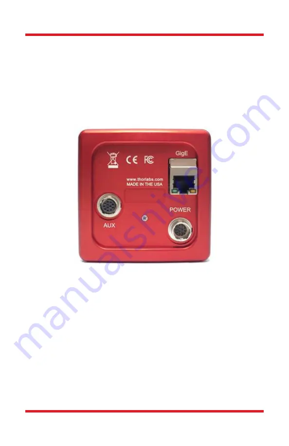
3.7.2.  Connections for a Gigabit Ethernet Scientific Camera  


To connect the camera, follow the steps below: 

1.  Plug the included power supply into a 100 

– 240 VAC mains outlet. 

2.  With the power supply turned off, connect the power supply to the 

POWER

 connector on the back of the camera. The connector on the 

camera is labeled is keyed to orient the connectors properly. 

3.  Connect the included 

Cat5e Gigabit Ethernet (GigE) Cable

: Connect the 

Ethernet cable to the port on the camera labeled “GigE”.  Connect the 
other end into the port of the Intel® Gigabit CT PCI Express desktop 
adapter, installed in the computer.  

4.  If external I/O signaling is required connect an 8050-CAB1 cable (not 

included) to the 

AUX

 port. 

Содержание DCC3260M

Страница 1: ...Thorlabs Digital Camera Quick Start Guide ...

Страница 2: ...Scientific USB 3 0 Installation 5 3 6 Installing the Software 5 3 6 1 Download the Software Installation Package 5 3 6 2 Driver Selection 6 3 7 Basic Connections 10 3 7 1 Connections for Standalone USB2 0 and USB3 0 Cameras 10 3 7 2 Connections for a Gigabit Ethernet Scientific Camera 10 3 7 3 Connections for a USB 3 0 Scientific Camera 11 3 7 4 Connections for a USB 3 0 Cooled sCMOS or CMOS Camer...

Страница 3: ...als are also available on the specific camera model web page at www thorlabs com 1 2 Receiving and Unpacking Your camera was thoroughly tested and carefully packed at the factory Once the camera shipment is accepted for delivery the carrier assumes full responsibility for its safe arrival Should you receive your shipment with any damage concealed or apparent please contact the carrier at once The ...

Страница 4: ...ly Make sure the included power cord is the correct type for the service you are connecting to AND connected to a properly grounded power outlet 100 240 VAC 50 60 Hz Transportation and delivery may cause the Digital Video Camera to be warm or cool upon receipt Please wait for the device to reach room temperature before attempting to operate There are NO user accessible fuses in this Digital Video ...

Страница 5: ...own cameras have a black and red aluminum case All Scientific Camera families have their own drivers Camera Link Gigabit Ethernet USB 3 0 and SDK Scientific Compact Scientific and Zelux Cameras DCC or DCU also referred to as DCx Compact USB Cameras are small with either a black stainless steel or grey plastic case depending on the model The DCx Camera family has its own USB drivers and SDK DCU DCC...

Страница 6: ...top computer systems Although the system will work with other adapters including laptop GigE adapters it is recommended that this card be used for optimal performance on all desktop installations 1 Power down the computer 2 Taking necessary precautions install the Intel PCI PCIe GigE adapter 3 Turn on the computer and accept Windows driver recommendations for the newly installed hardware 4 Run the...

Страница 7: ...are Installer follow the steps outlined in the next section including driver installation 2 If installing a PCIe USB3 0 card Power down the computer Taking necessary precautions install the USB 3 0 PCIe interface card Turn on the computer 3 Otherwise simply connect the camera to a USB3 0 port on the PC 4 Accept the driver installation recommendations for the newly installed hardware 5 Power on the...

Страница 8: ... 0 or 3 0 Gigabit Ethernet or Camera Link If you have more than one camera and with different interfaces select all that apply If you re unsure select them all Select a driver for installation by clicking on the dropdown and selecting either of the two choices Will be installed on local hard drive or Entire feature will be installed on local hard drive Both choices will install the driver If you d...

Страница 9: ...ation Depending on your PC s configuration and the drivers you selected you might encounter the additional Windows security dialogs below Be sure to click install to complete the operation otherwise the installer will roll back and exit Note Camera Link models are no longer sold by Thorlabs however the software still supports legacy products ...

Страница 10: ...abit Ethernet Driver Installation if selected Click Install Camera Link Driver Installation if selected Click Install Once setup is complete you may now proceed to the next section that will describe how to connect and power on your camera When the camera is connected and powered up you can navigate to the ThorCam Imaging Software as shown below ...

Страница 11: ...ge 9 Start All Programs ThorIabs Scientific Imaging ThorCam Figure 1 Thorlabs Start Menu Shortcuts Please refer to the model specific User Guide for more information on the additional items installed during this procedure including configuring the Gigabit Ethernet Driver for best performance ...

Страница 12: ...hernet Scientific Camera To connect the camera follow the steps below 1 Plug the included power supply into a 100 240 VAC mains outlet 2 With the power supply turned off connect the power supply to the POWER connector on the back of the camera The connector on the camera is labeled is keyed to orient the connectors properly 3 Connect the included Cat5e Gigabit Ethernet GigE Cable Connect the Ether...

Страница 13: ...ct the power supply to the POWER connector on the back of the camera The connector on the camera is keyed to orient the connectors properly 3 Connect the provided USB 3 0 cable into the mating USB port on the back of the camera The camera end of the cable will have two thumb screws Make sure the connector is fully inserted and then tighten the thumbscrews by hand into the camera housing Connect th...

Страница 14: ...ousing 2 Connect the provided 5V 3A power supply to the TEC Power port by threading the mating connector onto the camera s connector This provides power to the Thermal Electric Cooler Peltier device 3 Connect the other end of the USB 3 0 cable into a USB 3 0 port USB SS on the host computer Note The camera will turn on at this point 4 If external I O signaling is required connect an 8050 CAB1 cabl...

Страница 15: ...assemblies to be built into a unit by the user e g OEM laser driver cards Components Mechanics and optics Left over parts of units disassembled by the user PCB s housings etc If you wish to return a Thorlabs unit for waste recovery please contact Thorlabs or your nearest dealer for further information Waste Treatment is Your Own Responsibility If you do not return an end of life unit to Thorlabs y...

Страница 16: ...h care Do not use unnecessary force as this may damage the connectors Clean using a soft lint free cloth Use of isopropyl alcohol is permitted however do not immerse in any liquid or solvent Clean any accessible optical surfaces with an appropriate optics grade tissue or cloth 5 1 1 Service Only trained and approved Thorlabs personnel should service the system Please contact Thorlabs Technical Sup...

Страница 17: ...but the Camera is not Sending Data Normal Indicates that the Camera is Sending Data There is no Ethernet Connection Green Orange Normal Operation or 10 100Mbps Normal Operation or 10 100Mbps There is no Ethernet Connection LED If LED is On If LED is Flashing If LED is Off Link Blue Connected to USB 3 0 Port Green Connected to USB 2 0 Port Amber Camera has internal problem or the host computer port...

Страница 18: ...If LED is Off Status Blue Connected to USB 3 0 Port Green Connected to USB 2 0 Port Amber Camera has internal problem or the host computer port has malfunctioned USB port cannot provide sufficient power to the camera There is no USB Connection providing power to the camera LED If LED is On If LED is Flashing If LED is Off Status Blue Connected to a USB 3 0 Port Green Connected to a USB 2 0 Port Am...

Страница 19: ...Start Guide Chapter 6 Thorlabs Worldwide Contacts Rev S June 1 2020 Page 17 Thorlabs Worldwide Contacts For technical support or sales inquiries please visit us at www thorlabs com contact for our most up to date contact information ...

Страница 20: ...www thorlabs com ...

Отзывы: