8
3.4
AGC Adjustment
•
Apply a color bar pattern (RF Input) with 500
µ
V signal;
•
Connect a DC Voltmeter, in the AGC pin of the tuner;
•
Adjust
AGCT
to Zero and measure the voltage (V1);
•
Adjust
AGCT
so that the indication on the voltmeter be
(V1) - 1
± 0.2V.
3.5
Stereo Adjustment
•
For the adjustments, proceed according to illustration 2;
•
Adjust output indicated by “A” to tension equal to half of VCC plus 1V ;
•
Adjust
TC
to an indication in the microAmpère meter of 24
µ
A in the pin 17 of IC450;
•
Apply 300Hz/Mono/25KHz of deviation, 250mVrms, in the pin 29 of IC450;
•
Adjust SL to 500±20mVrms in the pins 15 and 38 of IC450;
•
Apply in the channel L=300Hz and in the channel R= 3k, 14% of generator Stereo modulation
DBX-NR (EIDEN BTSC );
•
Change
ADJ
from
0
to
1
. Check
A1
and
A2
after 1 second (if they varied);
•
After 1 second returns
ADJ
to
0
. The stereo circuit will align automatically.
ILLUSTRATION 2
3.6 Vertical Adjustment
•
Apply a circle Pattern Philips signal (RF Input)
•
Using the remote control, set the MAGIC mode “ORIGINAL”
Содержание CR14300
Страница 11: ...13 5 2 BLOCK DIAGRAM OF IC 101 TDA9380 ...
Страница 12: ...14 5 3 BLOCK DIAGRAM OF IC 490 BU4052 ...
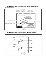
Страница 14: ...16 5 6 BLOCK DIAGRAM OF IC 450 STEREO DECODER ...
Страница 15: ...17 5 7 BLOCK DIAGRAM OF IC 430 LMC568 PLL SAP ____________________________________________ ...
Страница 64: ......
Страница 65: ......


