5
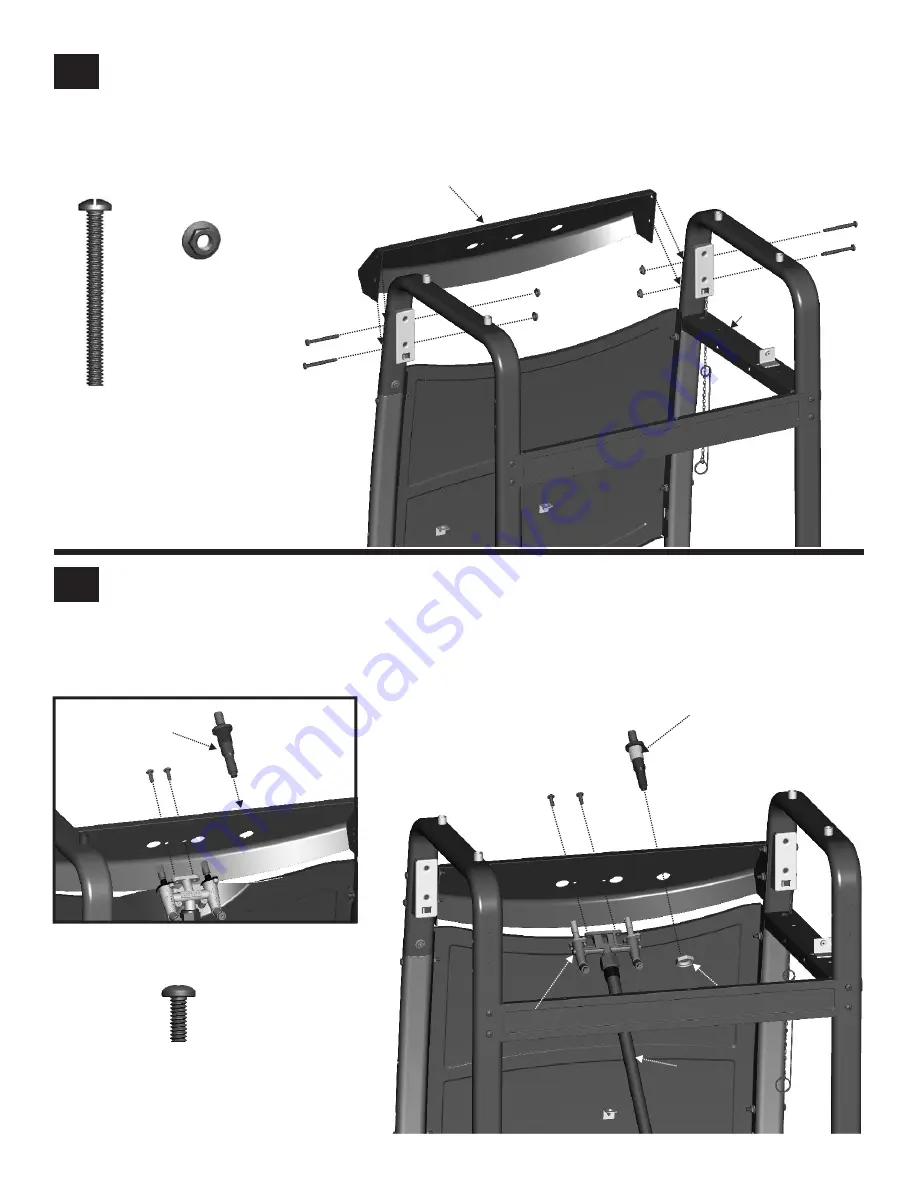
Control Panel
Stand cart upright.
In front, slide control panel between left and right legs, attach control panel with
#10-24x2’’ machine screws
and
#10-24
flange nuts
. Tighten all screws.
‘
‘
#10-24x2”
Machine Screw
Qty. 4
#10-24
Flange Nut
Qty.4
19
Control panel
Side Brace
6
Valve/Hose/Regulator and Ignitor
Attach v
‘
‘
Attach ignitor to control panel using the stamped nut that’s provided. NOTE: if your grill come with Snap-in ignitor, please
see Option.
alve/hose/regulator assembly to control panel with
#10-24x1/2’’ machine screws
.
#10-24x1/2”
Machine Screw
Qty. 2
Option: Snap the
ignitor into the
control panel
Ignitor
Ignitor
Stamped nut
Hose
Main burner valve
Содержание 461630510
Страница 16: ...B C Y F II G JJ H I J BB V S Q T X O AA A Z FF GG H J I P HH K D N V M L R U W CC EE DD E PARTS DIAGRAM 16 ...
Страница 28: ...NOTES 28 ...
Страница 29: ...NOTES 29 ...
Страница 30: ...NOTES 30 ...
Страница 31: ...31 Warranty Registration Department P O Box 1240 Columbus GA 31902 1240 ...
Страница 32: ......


