Installation, use and maintenance guide
ARDHEA EVO5
– ARDHEA-F EVO5
Page
15
ENG
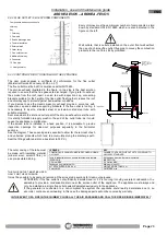
5.5 SCHEMATIC DIAGRAM OF TYPICAL CLOSED EXPANSION TANK HYDRAULIC SYSTEM WITH PUFFER
TANK
ATTENTION: it is mandatory to earth the generator. If this instruction is not observed serious damage, which
is not covered by warranty, will result to the body of the appliance. Have a skilled electrician check the
earthing. There must be no electric pote
ntial (Volt) between the generator earth and the system’s real earth
(earth plate). To prevent electrochemical corrosion of the appliance body do not use galvanised pipes and
fittings. Other materials must be earthed with special earthing cables in order to obtain a unipotential
earthing system.
ATTENTION:
Anti-condensation mixing valve should be set at approx. 65°C. So when the temperature of the boiler
drops below this value, the “cold” inlet closes and prevents circulation towards the puffer tank but only between the
boiler supply and return. In this way, the heat stored in the puffer tank is not dispersed to the boiler.
A
Supply to the puffer tank
SCA
Discharge
ACQ
Water main inlet
SCS
Safety heat exchanger
PC
System circulating pump
VEC
Additional closed expansion tank, sized to at least 10% of
the volume of water contained in the system
R
System return if integrated with a solar system
VM3VT
Anti-condensation mixing valve
R1
Return from the puffer tank
VNR
Nonreturn valve
S
On-off valve
VS
Safety valve 3 bar
SC
Gate valve
(throttle according to pressure drop in the system)
VST
Thermal relief valve
VASO CHIUSO -+ PUFFER
VNR
VEC
ACQ
VM3VT
SC
VNR
S
SCA
VS
A
R
S
S
S
COLD
MIX
H
O
T
R1
VST
SCS
PC


