background image

2

Terminator ZP/FAK-1

The following installation procedures are suggested guidelines 

for the installation of the Terminator ZP/FAK-1 Bulkhead Entry Kit.

Receiving, Storing and Handling 

1.  Inspect materials for damage incurred during shipping.
2.  Report damages to the carrier for settlement.
3.  Identify parts against the packing list to ensure the proper 

type and quantity has been received.

4.  Store in a dry location.

Provided by others — 8 each 8-32 stainless steel bolts, washers 

and nuts required. 

Tools Required                      

PETK Power and End Termination Kits (per heater)

PETK-1D

for BSX, RSX, VSX-HT

PETK-2D

for KSX, HTSX

PETK-3D

for FP, HPT

Required:

 Order Separately for each heater to be fabricated 

mm (inch)

mm (inch)

mm (inch)

D


inch (mm)

Terminator ZP/


FAK-1

220 mm 

(8-5/8”)

277 mm 


(11-7/8”)

107 mm 

(4-1/4”)

171 mm 

(6-3/4”)

D

B

A

C

8

7

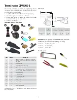
Terminator ZP/FAK-1 Kit Contents 

Item

Quantity

Description

1

1

Expediter Assembly: Flat Mount Base, Grommet, 

Threaded Grommet Compressor, and Support Cap 

with O-Ring

2

1

Junction Box Lid

3

1

Junction Box Base with O-Ring

4

1

Nut

5

1

Terminal Blocks with DIN Rail (Refer to terminal 

specifications for maximum allowable wire size)

6

1

Junction Box Cord

7

1

FAK-1 Cover (Top)

8

1

FAK-1 Cover (Bottom)

9

1

Heat Reflective Tape

10

2

RTV Sealant Tube

11

1

Glass Fiber Tape 

12

1

Silicone Gasket

13

1

Self-Vulcanizing Tape

1

2

4

3

6

5

9

10

11

12

13

Dimensions

Содержание Terminator ZP/FAK-1

Страница 1: ...Terminator ZP FAK 1 For Bulkhead Entry of Electrically Heated TubeTrace Bundles INSTALLATION PROCEDURES ...

Страница 2: ...VSX HT PETK 2D for KSX HTSX PETK 3D for FP HPT Required Order Separately for each heater to be fabricated A mm inch B mm inch C mm inch D inch mm Terminator ZP FAK 1 220 mm 8 5 8 277 mm 11 7 8 107 mm 4 1 4 171 mm 6 3 4 D B A C 8 7 Terminator ZP FAK 1 Kit Contents Item Quantity Description 1 1 Expediter Assembly Flat Mount Base Grommet Threaded Grommet Compressor and Support Cap with O Ring 2 1 Jun...

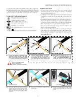
Страница 3: ...ndle as included from end of the tubing bundle Ensure sufficient heat trace is available for electrical connection See instructions included with heat trace PETK kit purchased separately 2a Strip back bundle insulation 38 mm 1 1 2 to 76 mm 3 beyond bus connection heat tracing If bus connection indentation is less than 305 mm 381 mm 12 15 from end of the heat tracing proceed stripping the bundle in...

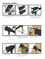
Страница 4: ...ket and work up over FAK ends FAK 1 Bottom Cover FAK 1 Top Cover RTV Sealant 12 Apply RTV bead to back of FAK 1 flange prior to securing to bulkhead RTV Bead Backside View Stainless Steel Bolts 14 Apply RTV bead around FAK 1 flange 13 Secure FAK 1 to bulkhead wall using 8 eight stainless steel bolts Note stainless steel bolts washers and nuts provided by others Recommended bolt size is 8 32 8 Asse...

Страница 5: ... junction box base Align Slots Dimple for Center Line Drilled thru 1 Wall 21 Completed Terminator ZP FAK 1 for bulkhead entry of electrically heated TubeTrace bundles Power Connection Bulkhead 17 Install quick mount terminal blocks twist to position and tighten screws By others for power connection application Terminal Blocks Typical 18 Complete system wiring between fabricated heat tracing and po...

Отзывы: