background image

Thermo Scientific

TSQ Altis, Quantis, and Fortis Hardware Manual

1

1

Introduction 

The TSQ Altis, TSQ Quantis, and TSQ Fortis MSs are triple quadrupole atmospheric 
pressure ionization (API) mass spectrometers. 

• Mass Spectrometry Models

• MS Mass-To-Charge Ratio Ranges

Mass Spectrometry Models

The MS models are the TSQ Altis, TSQ Quantis, and TSQ Fortis.

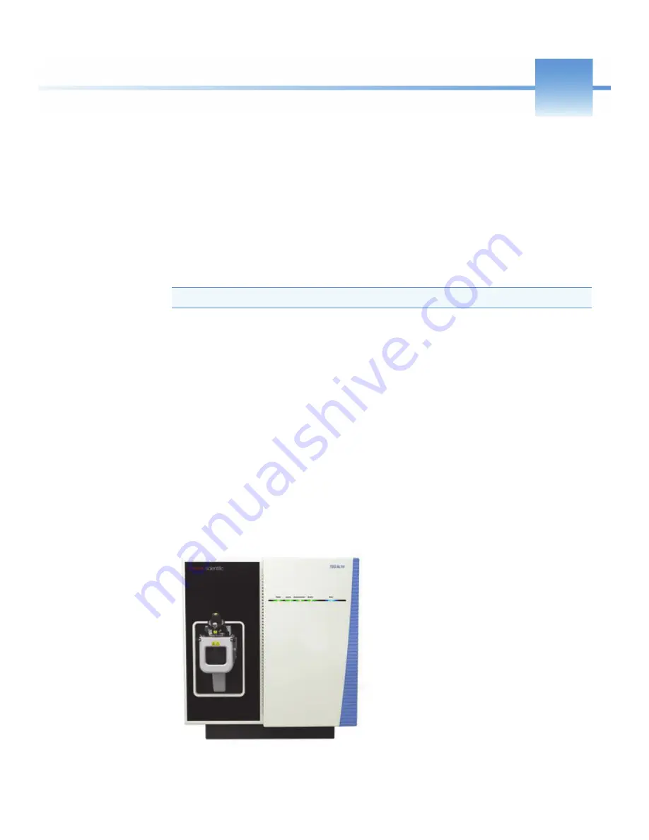
TSQ Altis MS

The TSQ Altis MS can address your most stringent analytical challenges for targeted 
quantitation workflows. The improved Active Ion Management (AIM™) technology, 
segmented quadrupoles, novel electron multipliers, and enhanced ion transmission tubes, 
help you to achieve unprecedented experimental sensitivity for all molecular species in 
complex matrices without sacrificing robustness. 

Note  

The 

Glossary

 defines some of the terms used in this manual.

Содержание TSQ Altis

Страница 1: ...TSQ Series II TSQ Altis TSQ Quantis and TSQ Fortis Hardware Manual 80111 97047 Revision A June 2018 ...

Страница 2: ...ration Rheodyne and Upchurch Scientific are registered trademarks of IDEX Health Science LLC Vespel is a registered trademark of E I du Pont de Nemours Co Viton is a registered trademark of DuPont Performance Elastomers LLC Chemyx is a trademark of Chemyx Inc MX Series II is a trademark of IDEX Health Science LLC All other trademarks are the property of Thermo Fisher Scientific Inc and its subsidi...

Страница 3: ...regulatory standards Follow all installation instructions provided in the documentation that comes with your system Order replacement parts as specified in the instrument manual and additional components options and periph erals directly from Thermo Fisher Scientific or an authorized representative FCC Compliance Statement Low Voltage Directive 2014 35 EU This device complies with Low Voltage Dire...

Страница 4: ...nce with international regulations This instrument must be used in the manner specified by Thermo Fisher Scientific to ensure protections provided by the instrument are not impaired Deviations from specified instructions on the proper use of the instrument include changes to the system and part replacement Accordingly order replacement parts from Thermo Fisher Scientific or one of its authorized r...

Страница 5: ...e you purchased the product Number of product pieces and the estimated total weight and volume Pick up address and contact person include contact information Appropriate pick up time Declaration of decontamination stating that all hazardous fluids or material have been removed from the product For additional information about the Restriction on Hazardous Substances RoHS Directive for the European ...

Страница 6: ......

Страница 7: ...Introduction 1 Mass Spectrometry Models 1 TSQ Altis MS 1 TSQ Quantis MS 2 TSQ Fortis MS 2 MS Mass To Charge Ratio Ranges 3 Chapter 2 Principles of Operation 5 Overview of the MS System 5 Overview of Ion Optics and Mass Analyzer 7 Chapter 3 Vacuum System 9 Vacuum Pumps 9 Vacuum Manifold 10 Vacuum System Block Diagram 12 Vacuum Gauges 13 Chapter 4 Internal Gas Supply 15 Chapter 5 Atmospheric Source ...

Страница 8: ...ter 10 Restarting the MS System After a Shutdown 35 Restarting the Data System 35 Restarting the Data System Using Windows 35 Restarting the Data System Using the Power Button 35 Resetting the Mass Spectrometer 36 Pumping the MS Down 37 Resetting Calibration Parameters 38 Starting the LC Gases and Autosampler 39 Chapter 11 MS Components On Off Status 41 Chapter 12 Maintaining the MS on a Daily Bas...

Страница 9: ...S 60 Check Mass Calibration 62 Mass Calibration 63 EM Gain Calibration 63 Tune and Mass Calibration 63 Calibration Solution Peak Values 64 Chapter 16 Optimizing the Compound Signal 67 Performing Compound Optimization Animation 67 Setting Up for Compound Optimization 67 Optimizing Parameters in the Optimization Pane 68 Chapter 17 Scan Types 71 Quadrupole Capacities 72 Summary of Scan Types 72 Full ...

Страница 10: ...he RF Lens Exit Lens MP00 RF Lens and Lens L0 Altis Quantis 97 Removing the Exit Lens MP00 and Lens L0 Fortis 99 Cleaning the RF Lens Exit Lens MP00 and Lens L0 100 Reinstalling the API Source Interface 101 Chapter 23 Maintaining the API Source Interface 103 Performing Source Maintenance Animation 103 Removing the Ion Sweep Cone and the Ion Transfer Tube 104 Cleaning the Spray Cone and O ring 107 ...

Страница 11: ...Inject Valve 129 About the Divert Inject Valve 129 Divert Inject Valve Configurations 130 Loop Injection 130 Divert Valve 131 Divert Inject Valve Controls 131 Appendix D Setting Up Sample Introduction Techniques 133 Setting Up H ESI or Low Flow H ESI Direct Infusion 133 Setting Up H ESI Direct Infusion 133 Setting Up Low Flow H ESI Direct Infusion 135 Setting Up High Flow Infusion Without an Autos...

Страница 12: ...Contents xii TSQ Altis Quantis and Fortis Hardware Manual Thermo Scientific ...

Страница 13: ...re 18 Communication connectors right side of the MS 28 Figure 19 Main power switch on the power module 32 Figure 20 Electronic service switch and main power switch 34 Figure 21 Reset button 1 on the communication panel 36 Figure 22 Electronic service switch and main power switch 37 Figure 23 Connection to the H ESI or the low flow H ESI source 52 Figure 24 Connection to the APCI spray insert 53 Fi...

Страница 14: ... the lens L0 and multipole MP00 from the MP00 L0 mount cage 100 Figure 53 Ion sweep cone removed from the MS mount assembly 104 Figure 54 Ion transfer tube removal tool TSQ Altis MS 105 Figure 55 Ion transfer tube removal tool TSQ Quantis MS 106 Figure 56 Ion transfer tube removal tool TSQ Fortis MS 106 Figure 57 Spray cone O ring ion transfer tube and ion sweep cone TSQ Quantis and TSQ Fortis 107...

Страница 15: ...Symbols and Cautions Contacting Us Suggesting Changes to the Documentation or to the Help Complete a brief survey about this document by clicking the button below Thank you in advance for your help Accessing Documentation The TSQ Altis TSQ Quantis and TSQ Fortis MSs include complete documentation For system requirements refer to the release notes on the software DVD Viewing the Product Manuals Win...

Страница 16: ...nt list click the browser Back button Special Notices Symbols and Cautions Make sure you understand the special notices symbols and caution labels in this guide Most of the special notices and cautions appear in boxes those pertaining to safety also have corresponding symbols Some symbols are also marked on the instrument itself and can appear in color or in black and white For complete definition...

Страница 17: ...e oil and when handling wetted parts of the instrument Hot surface Before touching the API source assembly allow heated components to cool Risk of electric shock This instrument uses voltages that can cause electric shock and or personal injury Before servicing shut down the instrument and disconnect it from line power While operating the instrument keep covers on Risk of eye injury Eye injury can...

Страница 18: ...To find global contact information or customize your request 1 Go to thermofisher com 2 Click Contact Us select the country and then select the type of support you need 3 At the prompt type the product name 4 Use the phone number or complete the online form To find product support knowledge bases and resources Go to thermofisher com us en home technical resources To find product information Go to ...

Страница 19: ...are the TSQ Altis TSQ Quantis and TSQ Fortis TSQ Altis MS The TSQ Altis MS can address your most stringent analytical challenges for targeted quantitation workflows The improved Active Ion Management AIM technology segmented quadrupoles novel electron multipliers and enhanced ion transmission tubes help you to achieve unprecedented experimental sensitivity for all molecular species in complex matr...

Страница 20: ...h its segmented quadrupoles faster rod drives and improved electron multipliers the TSQ Quantis MS delivers unprecedented robustness with best class sensitivity for everyday use and for every user TSQ Fortis MS The reliable instrument design intuitive software and comprehensive workflow solutions of the TSQ Fortis MS ensures superior productivity in the quantitation of hundreds of compounds of all...

Страница 21: ...tific TSQ Altis Quantis and Fortis Hardware Manual 3 MS Mass To Charge Ratio Ranges The TSQ Altis TSQ Quantis and TSQ Fortis MSs detect different ranges of mass to charge ratios Instrument m z Range in amu TSQ Altis 5 2000 TSQ Quantis 5 3000 TSQ Fortis 5 3000 ...

Страница 22: ...1 Introduction MS Mass To Charge Ratio Ranges 4 TSQ Altis Quantis and Fortis Hardware Manual Thermo Scientific ...

Страница 23: ...tics a triple stage mass analyzer and an ion detection system All are enclosed in a vacuum manifold except for part of the API source Overview of the MS System Overview of Ion Optics and Mass Analyzer Overview of the MS System Figure 1 Block diagram of MS hardware components 1 7 2 4 3 8 9 10 6 5 Data system Mass spectrometer Inlet ...

Страница 24: ...erates ions 3 Vacuum system Creates a vacuum for regions 4 5 6 and 7 4 Ion optics In the ion optics and mass analyzer the scan functions manipulate the ions 5 Mass analyzer 6 Ion detection systems As the ions strike the dynode detector they release a cascade of electrons These electrons generate a voltage signal 7 Instrument control electronic assemblies Control the MS components Data System 8 Mon...

Страница 25: ...c TSQ Altis Quantis and Fortis Hardware Manual 7 Overview of Ion Optics and Mass Analyzer The ion optic assemblies and the mass analyzer assemblies control the path of the ions from the ion source to the detector Figure 2 Ion optics and mass analyzer assemblies 8 11 7 3 5 1 9 2 10 4 6 ...

Страница 26: ...blocker and are removed from the ion beam 6 Quadrupole 1 The ions pass to quadrupole 1 Q1 which can act as a mass filter or as an ion transmission device Mass filter RF and DC voltages are applied and only the selected mass goes through The paths of the other ions become unstable and hit the rods Ion transmission device RF voltage is applied and all ions go through 7 Lenses EL21 EL22 EL23 Lenses E...

Страница 27: ...ifold Vacuum System Block Diagram Vacuum Gauges Vacuum Pumps Forepump Creates the vacuum necessary to properly operate the turbomolecular pump It also evacuates the ion transfer tube region of the vacuum manifold The TSQ Fortis MS and the TSQ Quantis MS each need one external foreline pump The TSQ Altis MS needs two external forepumps Turbomolecular pump Controls the vacuum for the vacuum regions ...

Страница 28: ...loses the API source interface ion optics mass analyzer and ion detection system assemblies It has multiple removable top cover plates various electrical feedthroughs and gas inlets Figure 3 Placement of the turbomolecular pump next to the vacuum manifold No Description No Description 1 Collision cell chamber 2 MP0 ion optics chamber 3 MP00 ion optics chamber 4 RF lens and ion transfer tube chambe...

Страница 29: ...al pressures Region Components Evacuated by Pressure TSQ Altis TSQ Quantis TSQ Fortis 1 API source N A Atmosphere Atmosphere Atmosphere 2 RF lens Forepump or forepumps 3 4 Torr 1 2 Torr 1 2 Torr 3 MP00 ion optics Triple inlet turbomolecular pump first inlet molecular drag 150 mTorr 120 mTorr 120 mTorr 4 MP0 ion optics Triple inlet turbomolecular pump second inlet interstage 2 mTorr 1 mTorr 1 mTorr...

Страница 30: ... 8 17 5 3 4 6 16 19 20 21 22 23 No Description No Description 1 Nitrogen gas port 2 Aux gas valve 3 Sheath gas valve 4 Sweep gas valve 5 Filtered air 6 Vent valve 7 Ion source 8 Sample tube 9 Atmospheric pressure region 10 Ion transfer tube and RF lens region 11 MP00 ion optics region 12 MP0 ion optics region 13 Mass analyzer region 14 Collision cell 15 Collision gas divert valve 16 Collision gas ...

Страница 31: ...auges Source pressure gauge Measures the pressure in the RF lens and API ion transfer tube region in the vacuum manifold and the foreline which connects the triple inlet turbomolecular pump and the forepump or forepumps Collision gas pressure gauge Measures the pressure in the collision cell Ionization gauge Measures the pressure in the analyzer region of the vacuum manifold The ionization gauge p...

Страница 32: ...3 Vacuum System Vacuum Gauges 14 TSQ Altis Quantis and Fortis Hardware Manual Thermo Scientific ...

Страница 33: ...MS through a 1 4 in port The valves for the sheath auxiliary and sweep gases control the flow of dry nitrogen gas into the API source Figure 5 Sheath gas is the inner coaxial nitrogen gas that helps nebulize the sample solution into a fine mist as the solution exits the API spray insert nozzle Auxiliary gas is the outer coaxial nitrogen gas that helps the sheath gas to nebulize and evaporate the s...

Страница 34: ...Quantis and Fortis Hardware Manual Thermo Scientific Figure 5 Gas inlets and vacuum foreline port left side of the MS No Description No Description 1 Argon gas inlet 2 Nitrogen gas inlet 3 Drain Waste Port 4 Vacuum foreline port 1 4 2 3 ...

Страница 35: ...Thermo Scientific TSQ Altis Quantis and Fortis Hardware Manual 17 5 Atmospheric Source Interface API Source Interface Overview Ion Transfer Tube RF and Exit Lens ...

Страница 36: ... sweep cone is a metal cone over the ion transfer tube It channels the sweep gas toward the ion transfer tube entrance acts as a physical barrier protecting the entrance and increases source robustness The result is a significant increase in the number of samples to analyze without a loss of signal intensity In addition keeping the ion transfer tube entrance as clean as possible reduces the need f...

Страница 37: ...e 7 Altis ion transfer tube Figure 8 Quantis ion transfer tube Figure 9 Fortis ion transfer tube The heater block contains two heater cartridges that surround the ion transfer tube and heat the tube to temperatures up to 400 C 752 F A decreasing pressure gradient draws ions into the ion transfer tube in the atmospheric pressure region When you remove the ion transfer tube after it has cooled to ro...

Страница 38: ...Q Fortis MS has just an exit lens Figure The MS applies an RF voltage to the electrodes and the adjacent electrodes have voltages of opposite phase As the RF amplitude increases ions of progressively higher m z values pass through to the exit lens and move toward the MP00 RF lens The exit lens acts as a vacuum baffle between the higher pressure API source interface region and the lower pressure MP...

Страница 39: ...5 Atmospheric Source Interface RF and Exit Lens Thermo Scientific TSQ Altis Quantis and Fortis Hardware Manual 21 Figure 12 Fortis exit lens No Description No Description 1 Exit lens 2 Tube lens 1 2 ...

Страница 40: ...5 Atmospheric Source Interface RF and Exit Lens 22 TSQ Altis Quantis and Fortis Hardware Manual Thermo Scientific ...

Страница 41: ...F voltage to the elements to generate an electric field that guides the ions along the axis of the lens The lens L0 is a metal disk with a small hole in the center through which the ion beam passes The MS applies an electrical potential positive for positive ions and negative for negative ions to lens L0 to transmit ions of the selected charge Lens L0 acts as a baffle between MP00 and MP0 to isola...

Страница 42: ...the rods Neutral species do not follow the curve instead they strike the neutral beam blocker and are removed from the beam The EL11 and EL12 lenses are metal disks with a circular hole in the center through which the ion beams passes Figure 15 They act as a two element cone lens The MS applies an electrical potential to the lens to accelerate or decelerate ions as they approach each lens The EL11...

Страница 43: ...for their descriptions Figure 16 LEDs on the instrument front panel Table 2 LEDs for the MSs LED State Description Power Green The MS is receiving power The electronics service switch is in the Operating Mode position Off The MS is not receiving power The electronics service switch is in the Service Mode position Vacuum Green The vacuum is within the allowable operating range Yellow The vacuum is ...

Страница 44: ...unicating Yellow The MS and data system are trying to establish a communication link Off The MS is off System Green The MS is on Yellow The MS is in standby mode Off The MS is off Scan Flashing blue The MS is on and scanning Off The MS is not scanning Table 2 LEDs for the MSs LED State Description No Description No Description 1 Electronics service switch 2 SV65 Pump Enable connector forepump on o...

Страница 45: ... and off by using the relay control cable that connects to the SV65 Pump Enable connector Communications Panel The communications panel which is located on the right side of the MS provides a system Reset button a contact closure interface Peripheral Control an analog input connector USB ports for the external syringe pump and divert inject valve and a Gigabit Ethernet connection port for the data...

Страница 46: ... Altis Quantis and Fortis Hardware Manual Thermo Scientific Figure 18 Communication connectors right side of the MS No Description No Description 1 Ethernet port 2 USB ports 3 Analog Input connector 4 Peripheral Control connector 5 Reset button 1 2 3 4 5 ...

Страница 47: ...activate this signal the external device must pull the signal either low below 0 75 Vdc or high above 2 4 Vdc depending on the polarity for at least 100 ms by using a relay an open collector driver or a similar device that connects between pins 4 and 1 Note In the Instrument Configuration window set the contact closure signal to High to low edge or Low to high edge whichever matches the setting fo...

Страница 48: ...he input voltage 1 Chassis Earth ground for pins 3 and 4 3 4 2V Max positive pin 3 and negative pin 4 Provides a connection for an external device such as an LC instrument Input 0 2 Vdc voltage clamps at 5 Vdc 5 Chassis Earth ground for pins 7 and 8 7 8 10V Max positive pin 7 and negative pin 8 Provides a connection for an external device such as an LC instrument Input 0 10 Vdc voltage clamps at 1...

Страница 49: ... syringe pump the LC pumps and the autosampler Placing the MS in Standby Mode If you are not going to use the MS for a few days place it in standby mode 1 Open the Tune window Windows 7 From the Microsoft Windows taskbar choose Start All Programs Thermo Instruments model x x model Tune to open the Tune window Windows 10 From the Windows taskbar choose Start All Apps Thermo Instruments model x x mo...

Страница 50: ...nd ion optic RF voltages For a more complete list refer to Chapter 11 MS Components On Off Status Shutting Down the MS System in an Emergency 1 To turn off the MS in an emergency turn off the main power switch 1 in Figure 19 on the power panel on the right side of the MS Figure 19 This switch turns off all power to the MS including the forepump without harming components within the instrument If y...

Страница 51: ...lacing the MS in Standby Mode 2 Find the electronics service switch on the right side power panel Figure 20 3 Switch it into the Service Mode down position This turns off all LEDs on the front panel and the power to the nonvacuum system electronics 4 Turn off the Main Power switch The ion transfer tube heater and the ion optics voltages turn off All power to the MS including the turbomolecular pum...

Страница 52: ...ampler 1 If the LC system is included turn it off as described in the LC manual 2 Turn off the argon and nitrogen gas supplies at their tanks 3 Shut down the data system computer and turn off the monitor 4 If an autosampler and printer are included use their On Off switches to turn them off No Description 1 Electronics service switch service mode 2 Main power switch off 2 1 CAUTION Do not disconne...

Страница 53: ...roperly close applications and save changes to any open application Restarting the Data System Using Windows 1 On the Windows taskbar choose Start and then click the arrow next to Shut Down 2 Choose Restart and then click OK Restarting the Data System Using the Power Button 1 Press the power button on the data system computer 2 Wait at least 20 seconds 3 Press the power button again Note After you...

Страница 54: ...t side communication panel for 3 seconds Figure 21 Reset button 1 on the communication panel The following occurs The embedded computer restarts All LEDs on the front panel turn off except the Power LED After several more seconds the Communication LED turns yellow and then green to indicate that the MS and the data system are communicating The data system transfers operational software to the MS A...

Страница 55: ...electronics service switch is in the Service Mode position 2 Plug in the power cord for the MS 3 Turn on the Main Power switch This turns on the forepump or forepumps and the turbomolecular pumps All LEDs on the front panel are off 4 Wait 15 minutes before you place the electronics service switch in the Operating Mode up position 5 Wait at least 15 hours for the pumps to create sufficient vacuum F...

Страница 56: ...MS enters operating mode Power Green Vacuum Communication System Off MS startup completed Vacuum Communication Green System Yellow IMPORTANT On the front panel the Vacuum LED illuminates green only when the pressure in the mass analyzer region as measured by the ionization gauge is below the maximum allowable pressure of 1 10 4 Torr MS Source pressure Analyzer pressure TSQ Altis 4 5 Torr 9 0 10 6 ...

Страница 57: ... procedure described in the manufacturer s manual 2 Turn on the autosampler by using its on off power switch If necessary configure the autosampler For procedures for placing sample vials preparing solvent and waste containers installing syringes and so on refer to the autosampler manual 3 Check that the valves of the argon and nitrogen gases are open Note Do not turn on the liquid flow to the MS ...

Страница 58: ...10 Restarting the MS System After a Shutdown Starting the LC Gases and Autosampler 40 TSQ Altis Quantis and Fortis Hardware Manual Thermo Scientific ...

Страница 59: ...ents voltages and API gas flows Sheet 1 of 2 Mass spectrometer component Standby mode Offa mode Electronics service switch Service Mode position Main Power switch Off 0 position Vent valve Closed Closed Closed Open APCI corona discharge needle Off Off Off Off Conversion dynode Electron multiplier ESI needle Gas argon collision CID gas b Power supply electron multiplier and conversion dynode Vapori...

Страница 60: ...on vacuum mass analyzer Fans On Forepumps Gauge convection vacuum foreline Turbomolecular pump and controller Vent Delay PCB a The electronics service switch is in the Operating Mode up position b You can control this setting in your method even when the instrument is in standby mode c In standby mode the Tune application sets the API gases to their standby default settings 2 arbitrary to keep the...

Страница 61: ...cate insufficient pressure levels to turn on the system In the Tune window a green square indicates that the readback value is good Possible causes of a major leak might be a loose or disconnected fitting an improperly positioned O ring or an open valve 1 Listen for a rush of air or a hissing sound coming from the MS If you do not hear these sounds there is no air leak If you hear these sounds con...

Страница 62: ... to Vacuum 3 Compare the current values of the pressures in the vacuum manifold with the values listed in Table 6 for the TSQ Altis MS Table 7 for the TSQ Quantis and Table 8 for the TSQ Fortis MS If the values are higher than normal you might have an air leak CAUTION For proper performance operate the system at the proper vacuum levels Poor vacuum levels can cause reduced sensitivity and reduced ...

Страница 63: ...onditions Source Pressure foreline ion transfer tube Tube lens Skimmer Region Analyzer analyzer region after pumping for at least 12 hours Collision gas off ion transfer tube orifice sealed Less than 0 05 Less than 6 10 6 Collision gas off ion transfer tube orifice open Less than 2 0 Less than 9 10 6 Collision gas set to 1 5 mTorr ion transfer tube orifice open Less than 2 0 Approximately 3 10 5 T...

Страница 64: ... necessary adjust the pressure with the tank pressure regulator Nitrogen 1 Using the regulator of the nitrogen gas tank or liquid nitrogen boil off tank make sure that there is sufficient gas for the analysis Based on 24 hour per day operation typical nitrogen consumption is 2800 liters per day 100 ft3 day If necessary replace the tank 2 Verify that the pressure of nitrogen gas reaching the MS is ...

Страница 65: ...syringe pump 2 Place the MS in Standby mode 3 Remove the syringe from the syringe pump as follows a Lift the syringe holder off of the syringe b Press the pusher block s release button and slide the block to the left c Remove the syringe from the holder d Carefully remove the syringe needle from the Teflon tube on the syringe adapter assembly 4 Rinse the syringe with a solution of 50 50 methanol w...

Страница 66: ...he inlet components Daily purging of the oil removes water and other dissolved chemicals which can cause corrosion and decrease forepump performance over its lifetime Refer to the forepump s documentation Make sure to close the purge valve before continuing normal operation Emptying the Solvent Waste Container Check the solvent level in the solvent waste container daily If necessary empty the cont...

Страница 67: ...temp C Vaporizer temp C Nitrogen use L min Sheath Auxiliary Sweep Up to 15 Pos 3500 Neg 2500 5 2 0 Altis 325 Quantis 275 Fortis 275 20 3 5 16 99 25 5 0 75 8 0 100 199 35 7 0 Altis 325 Quantis 300 Fortis 300 275 10 5 200 500 50 10 1 Altis 325 Quantis 300 Fortis 300 350 15 0 LC flow rate μL min Sheath gas arbitrary units Auxiliary gas arb units Sweep gas arb units Ion transfer tube temp C Vaporizer ...

Страница 68: ...idelines for LC NSI MS Parameters 50 TSQ Altis Quantis and Fortis Hardware Manual Thermo Scientific Guidelines for LC NSI MS Parameters Spray voltage V Sweep gas arb units Ion transfer tube temp C Positive mode 1200 0 325 Negative mode 600 ...

Страница 69: ...you turn the power on Note Use the fittings PEEK or Viper that are appropriate for your application The illustrations are examples only Note Refer to the OptaMax NG Ion Source User Guide for more information CAUTION If liquid is leaking out of a tube or a fitting it may be electrically live and could cause an electric shock when touched Turn off the power to the source before fixing the leak Turn ...

Страница 70: ...tting to connect the other end of the red PEEK tubing 3 to the H ESI or the low flow H ESI spray insert 4 Connecting the Sample Flow to the APCI Source Connect the APCI spray insert to the sample introduction method If you have the inlet plumbed for H ESI you can leave the grounding union in place You will not use it Use tubing red PEEK or natural PEEK nano Viper with a fingertight fitting to conn...

Страница 71: ...urce Connecting the Sample Flow to the APCI Source Thermo Scientific TSQ Altis Quantis and Fortis Hardware Manual 53 Figure 24 Connection to the APCI spray insert No Description 1 Tubing from sample flow red PEEK or natural PEEK nano Viper 1 ...

Страница 72: ...14 Connecting the Sample Flow to the Source Connecting the Sample Flow to the APCI Source 54 TSQ Altis Quantis and Fortis Hardware Manual Thermo Scientific ...

Страница 73: ...pendix B Setting Up the Syringe with the Syringe Pump Risk of electric shock This instrument uses voltages that can cause electric shock and or personal injury While operating the instrument keep the covers on CAUTION Do not wear nitrile gloves when you are working with the calibration solution EMRS Nitrile gloves are made with diphenylguanidine which is soluble in EMRS If diphenylguanidine contam...

Страница 74: ...the Favorites pane under System Settings right click Default for EMRS Calibration with Positive Polarity and choose Apply The default parameter settings appear at the top of the Favorites pane 4 Set the syringe pump parameters as follows a Click Syringe Off to turn on the syringe pump The button name changes to Syringe On b Click the arrow next to the Syringe On Off button to open the syringe pump...

Страница 75: ...n 7 Verify that the system readback is normal Determining the Initial API Source Settings These initial setting are a starting point for calibrating and optimizing system performance 1 In the Tune window click the Ion Source tab 2 In the Current LC Flow μL min box type the flow rate from Table 11 and then click Get Defaults 3 Click Apply The Tune application makes a change in the History pane Tabl...

Страница 76: ...1 In the Define Scan pane Figure 27 set the following parameters Scan Type SIM Q1 Scan Range m z 622 602 in Negative Mode Source Fragmentation V 30 Figure 26 Define Scan parameters 2 Check the H ESI probe position is as follows Depth low to medium Front to back position closest to the MS entrance Side to side position center closest to the MS entrance 3 Place the MS in On mode Parameter Value Curr...

Страница 77: ...negative mode in the Mass column d To plot the specified chromatogram click OK The Plot Chromatogram tool generates a real time graph plot where you can observe the signal stability and the effects of changes to various parameters The tool also generates a real time graph of the RSD for a 10 Da selected ion monitoring SIM scan that is centered around the most abundant mass to charge ratio m z in t...

Страница 78: ... rate of EMRS Before you calibrate the MS follow the procedure Evaluating the Spray Stability 1 Set the syringe pump to infuse the EMRS at 5 μL min into the API source 2 Place the MS in On mode 3 In the Define Scan pane select Full Scan Q1 or Full Scan Q3 4 Set the scan range to 50 1650 Note When the MS completes a calibration the Tune application writes the calibration parameters and the mass dep...

Страница 79: ...ne of the Calibration options Before you run each of these options the system evaluates the spray stability Check Mass Calibration Mass Calibration EM Gain Calibration Tune and Mass Calibration 7 Click Start When the calibration is complete the Tune application prompts you to generate a report of the calibration results Figure 29 Report Generation Options 8 Select an option and click OK 9 After th...

Страница 80: ...s of 0 2 Da TSQ Altis MS only 0 4 Da and 0 7 Da and for quadrupoles Q1 and Q3 Figure 30 shows the error range boxes for the EMRS calibrants The y axis is the error range of the peak widths from the expected peak width of 0 7 Da and the x axis is the error range of the mass positions from the expected mass position in Da The MS measures the peak width and mass position over a large number of scans ...

Страница 81: ...ent scan rates 250 500 and 1000 Da sec and for quadrupoles Q1 and Q3 EM Gain Calibration If you notice a falloff of the ion signal intensity use the EM Gain Calibration option Figure 28 to increases the voltage on the electron multiplier This will maintain a gain of 1 105 for MS mode and 1 106 for MS MS mode Tune and Mass Calibration When you select the Tune and Mass Calibration option Figure 28 t...

Страница 82: ... m z values close to the following theoretical values Figure 32 Mass spectrum of EMRS in positive ion mode Positive mode m z Negative mode m z 69 69 102 113 215 302 622 602 922 1034 1522 1634 IMPORTANT If you observe interfering peaks in the EMRS spectrum that are within 10 Da of any of these calibration masses follow the procedure Flushing the Inlet Components on page 47 Ensure that the interferi...

Страница 83: ...15 Calibrating the MS Calibrating and Tuning the MS Thermo Scientific TSQ Altis Quantis and Fortis Hardware Manual 65 Figure 33 Mass spectrum of EMRS in negative ion mode ...

Страница 84: ...15 Calibrating the MS Calibrating and Tuning the MS 66 TSQ Altis Quantis and Fortis Hardware Manual Thermo Scientific ...

Страница 85: ...og tab and then the instrument name 4 Scroll down until you see the Product overview Videos and Documents tab 5 Click the Videos tab and on the right click Performing compound optimization Setting Up for Compound Optimization You optimize the signal of the compound with the LC conditions used to analyze it This is a high flow infusion technique in which a Tee union directs the analyte from the syr...

Страница 86: ...des and specify the adducts to include For descriptions of the Optimization parameters refer to the Tune Help c In the Source Optimization list select On and then select the Spray Voltage Sheath Gas Aux Gas and Sweep Gas check boxes that appear d For a SIM scan select the Source Fragmentation RF Lens and Precursor Ion Mass check boxes For an SRM scan also select On in the Product Ion Optimization ...

Страница 87: ...ation Table add a row for each compound and modify the column values as applicable 5 Place the system in On mode and then click Start After the compound optimization is complete you can view and save the generated report for each compound Figure 35 shows an example of in progress graphs and spectra Figure 36 shows the Optimization Results table Tip If there are multiple syringes enter the syringe ...

Страница 88: ...ure 35 shows the Optimization Results Table Figure 35 Example optimization of the RF lens SRIG RF tuning for m z 997 55 After the optimization is complete the Acquisition Table appears which contains links to an optimization report and raw data file for each optimized compound The Optimization Results and Source Optimization Results tables also appear displaying the optimized parameter values Figu...

Страница 89: ... types full scan Q1 full scan Q3 selected ion monitoring SIM scan Q1 and SIM scan Q3 MS MS scan types product ion scan precursor ion scan neutral loss scan and selected reaction monitoring SRM scan type The available modes depend on the number and type of rod assemblies and the voltages applied to the rod assemblies Quadrupole Capacities Summary of Scan Types Full Scan Q1 and Q3 Scan Types Selecte...

Страница 90: ...drupole rod assemblies can operate with both RF and DC voltages or with only RF voltage That is Q1 and Q3 can act as either mass analyzers or ion transmission devices The Q2 rod assembly operates exclusively with RF voltage Therefore Q2 is always an ion transmission device Summary of Scan Types 1 A rod assembly is a regular array of metal rods See Mass Analyzers Table 13 Summary of scan types Scan...

Страница 91: ...u perform a SIM or an SRM experiment you must know what ions or reactions you are looking for Therefore you might use a full scan for SIM to determine the identity of an analyte and to obtain its mass spectrum and a full scan for SRM to determine the mass spectrum and product mass spectra for precursor ions of interest Then you might use SIM or SRM to do routine quantitative analysis of the compou...

Страница 92: ...present in the collision cell This latter step is known as collision induced dissociation CID Ions formed in the collision cell enter the product mass analyzer Q3 for the second stage of mass analysis The product mass analyzer is scanned to obtain a mass spectrum that shows the product ions produced from the fragmentation of the selected precursor ion Experiments that use a product ion scan type c...

Страница 93: ...um note that data for the m z axis is obtained from Q1 the precursor ions whereas data for the ion intensity axis is obtained from Q3 from monitoring the product ion Figure 38 Illustration of the precursor scan type You can use experiments that employ the precursor scan type precursor experiments in structure and fragmentation studies as well as in survey analyses of mixtures In general precursor ...

Страница 94: ...erefore a neutral loss mass spectrum is a spectrum that shows all the precursor ions that lose a neutral species of a selected mass You can also perform a neutral gain or association experiment in which the mass range scanned by Q3 is offset by a selected mass above the mass range scanned by Q1 For a neutral loss or neutral gain mass spectrum as for a precursor mass spectrum Q1 the precursor ion p...

Страница 95: ...SRM monitors a limited number of precursor product ion pairs As does SIM SRM provides for the very rapid analysis of trace components in complex mixtures However because SRM selects two sets of ions it obtains greater selectivity compared to SIM Any interfering compound would have to form a precursor ion of the same m z as the selected precursor ion from the target compound Furthermore that precur...

Страница 96: ...17 Scan Types Selected Reaction Monitoring Scan Type 78 TSQ Altis Quantis and Fortis Hardware Manual Thermo Scientific ...

Страница 97: ...terval The intensity at each sampling interval is displayed with the intensities connected by a continuous line Profile data is a good way to see the isotopic distribution especially for higher charged ions Centroid data With centroid data you see the mass spectrum as a bar graph Centroid gives you a reliable readback of the measured m z This scan data type sums the intensities of each set of samp...

Страница 98: ... transmitted to the mass analyzer for mass analysis by changing the polarity of the voltage potentials applied to the API source ion optics and ion detection system The information obtained from a positive ion mass spectrum is different from and complementary to the information from a negative ion spectrum Therefore the ability to obtain both positive ion and negative ion mass spectra aids you in ...

Страница 99: ...hod Animation 1 Go to thermofisher com 2 In the search field type TSQ Altis TSQ Quantis or TSQ Fortis 3 Click the Catalog tab and then the instrument name 4 Scroll down until you see the Product overview Videos and Documents tab 5 Click the Videos tab and on the right click Performing compound optimization Note Before you begin check the following In the Calibration pane ensure that all calibratio...

Страница 100: ...amp suffix that consists of the year YYYY month MM day DD and time HHMMSS c In the Sample Name box type the name of the analyte or other suitable label d In the Comment box type a comment about the experiment For example describe the ionization mode scan type scan rate sample amount or method of sample introduction The data system includes the comment in the header information for the raw data fil...

Страница 101: ... settings the data acquisition process begins and the small circle on the Record button turns red 5 When you are ready click Record again to stop the acquisition The small circle on the Record button turns gray not recording For more information about reviewing the acquired data refer to the Thermo FreeStyle or the FreeStyle Help No Description 1 Click to open close the Data Acquisition pane 2 Fil...

Страница 102: ...as part of the Xcalibur sequence setup Follow these procedures 1 Selecting the External Start Instrument 2 Acquiring Data Files with the Xcalibur Data System Selecting the External Start Instrument 1 Open the Xcalibur data system and then choose View Sequence Setup View to open the Sequence Setup window 2 Open the sequence that you want to run as follows a Click the Open button and browse to the a...

Страница 103: ...ments to open the Change Instruments In Use dialog box Figure 44 Figure 44 Change Instrument in Use dialog box a In the Instrument column click the arrow in the column on the left of the instrument and select the device b Click OK 4 In the Run Sequence dialog box complete the remaining selections 5 Click OK This completes the start instrument setup Acquiring Data Files with the Xcalibur Data Syste...

Страница 104: ...peptide analysis PA From Xcalibur Instrument Setup window you can use the Method Editor to create an instrument method for your experiment 1 Open the system template designed for the experiment type that you want to perform 2 Enter the parameters specific to the experiment 3 Save the entries as part of an Xcalibur instrument method meth file name extension For additional information refer to the H...

Страница 105: ...Fortis may use different parts The required parts for each MS system are noted in each procedure For a list of replaceable parts see Appendix E Replaceable Parts CAUTION Heavy object Never lift or move the instrument by yourself you can suffer personal injury or damage the instrument CAUTION Before performing instrument maintenance either shut down the MS completely or place it in Standby mode as ...

Страница 106: ...e the H ESI needle insert If the metal needle is obstructed Replace the APCI fused silica tubing If the tubing is obstructed API source interface Clean the ion sweep cone and spray cone Daily or more often depending on analytical conditions page 103 Remove and clean the ion transfer tube Weekly or if the ion transfer tube bore is contaminated or obstructed Replace the ion transfer tube If the bore...

Страница 107: ...uires few tools to perform routine maintenance procedures You can remove and disassemble many of the components by hand Table 15 lists the necessary chemicals tools and equipment for maintaining the instrument One of the tools is in the TSQ Source Installation Kit In addition you can use the contents of the PM Cleaning Kit P N 70111 62112 IMPORTANT Make sure that you do not introduce any scratches...

Страница 108: ...h chemical you use Store and handle all chemicals in accordance with standard safety procedures Always wear protective gloves and safety glasses when you use solvents or corrosives Also contain waste streams use proper ventilation and dispose of all laboratory reagents according to the directions in the MSDS or SDS Table 15 Chemicals tools and equipment Sheet 1 of 2 Description Part number Chemica...

Страница 109: ... free and powder free Fisher Scientific 19 120 2947 Unity Lab Services 23827 0008 size medium 23827 0009 size large Industrial tissues lint free Magnification device MICRO MESH polishing swabs 6000 grit light purple color 2 25 in long 00725 01 00027 Sonicator Table 15 Chemicals tools and equipment Sheet 2 of 2 Description Part number ...

Страница 110: ...20 Maintenance Schedule and Supplies Tools and Supplies 92 TSQ Altis Quantis and Fortis Hardware Manual Thermo Scientific ...

Страница 111: ...l Thermo Fisher Scientific service engineer 1 After the API source cools to room temperature remove it from the MS 2 Put on appropriate personal protective equipment in particular safety glasses and chemical resistant gloves 3 Under an appropriate fume hood rinse the interior of the housing with lint free tissues sprayed with UHPLC MS grade methanol 4 Allow the housing to dry before you install it...

Страница 112: ...21 Maintaining the API Source and Replacing the H ESI Needle Replacing the H ESI Needle 94 TSQ Altis Quantis and Fortis Hardware Manual Thermo Scientific ...

Страница 113: ... RF Lens Exit Lens MP00 RF Lens and Lens L0 Altis Quantis Removing the Exit Lens MP00 and Lens L0 Fortis Cleaning the RF Lens Exit Lens MP00 and Lens L0 Reinstalling the API Source Interface Removing the API Source Interface You must remove the API source interface so that you can remove and clean the RF lens exit lens MP00 and Lens L0 1 Shut down and vent the system and let it cool to room temper...

Страница 114: ...ving and Installation the API Source 4 Lift up the release latch and firmly push it to unseal the API source interface from the vacuum manifold 5 Grasp the API source interface with your fingers and then carefully pull it out of the vacuum manifold Figure 46 Figure 46 API source interface removed from the vacuum manifold CAUTION Do not disconnect the power supply cord from the MS while the other e...

Страница 115: ...le MP00 and lens L0 to the cage 3 Pull the MP00 and lens L0 assembly off of the API source interface cage See Figure 47 and Figure 48 Place them on a clean lint surface 4 Grasp the two Allen screws and carefully pull the RF lens with the exit lens straight out of the API source interface cage 5 Remove the exit lens off of the RF lens Place both on a clean surface 6 Using the lens L0 removal tool o...

Страница 116: ...ntific Figure 48 Removing the RF lens and exit lens TSQ Quantis MS Figure 49 Removing the lens L0 and multipole MP00 from the MP00 L0 mount cage No Description No Description 1 API source interface cage 2 Allen screws loosened and extended 3 Lens L0 4 Multipole MP00 and lens L0 No Description No Description 1 Rf lens and exit lens assembly 2 Exit lens 1 2 MP00 RF lens Multiple MP00 Lens L0 ...

Страница 117: ...d the two captive Allen screws that secure multipole MP00 and lens L0 to the cage 3 Pull the multipole MP00 and lens L0 assembly off of the API source interface cage See Figure 50 Place them on a clean lint free surface Figure 50 Removing the multipole MP00 and lens L0 assembly TSQ Fortis 5 Grasp the two Allen screws and carefully pull the exit lens straight out of the API source interface cage No...

Страница 118: ...ure 52 Removing the lens L0 and multipole MP00 from the MP00 L0 mount cage Cleaning the RF Lens Exit Lens MP00 and Lens L0 1 Using a magnification device inspect the components for any lint particulates and sample buildup or coatings 2 For 10 minutes sonicate the components in either a 50 50 solution of methanol water or a 1 solution of Liquinox in water No Description No Description 1 Allen screw...

Страница 119: ...e the components with methanol 9 Dry the components thoroughly with nitrogen gas 10 Using a magnifying device inspect the components for any residual lint or particulates To reinstall the RF lens exit lens multipole MP00 and lens L0 1 Attach the exit lens to the RF lens and then reinsert the RF lens into the API source interface cage Figure 48 2 Reassemble the multipole MP00 and lens L0 assembly 3...

Страница 120: ...22 Maintaining the RF Lens Exit Lens MP00 RF Lens and Lens L0 Reinstalling the API Source Interface 102 TSQ Altis Quantis and Fortis Hardware Manual Thermo Scientific ...

Страница 121: ... ring 3 Cleaning the Ion Transfer Tube 4 Cleaning the Ion Sweep Cone Performing Source Maintenance Animation 1 Go to thermofisher com 2 In the search field type TSQ Altis TSQ Quantis or TSQ Fortis 3 Click the Catalog tab and then the instrument name 4 Scroll down until you see the Product overview Videos and Documents tab Click the Videos tab and on the right click Performing source maintenance CA...

Страница 122: ...robably the cause 1 Turn off the liquid flow to the API source 2 In the Tune application place the MS in Standby mode 3 In the Ion Source pane set the Ion Transfer Tube Temperature and Vaporizer Temperature to 50 C or less and observe the readback temperatures 4 Turn the system off Figure 53 Ion sweep cone removed from the MS mount assembly CAUTION Hot surface The external surface of the spray ins...

Страница 123: ...stom removal tool with the flat edges on the exposed tip of the ion transfer tube and then do one of the following TSQ Altis MS Rotate the tool 1 in Figure 54 counterclockwise When the tube is free of the spray cone use the hook flat edges on the tool 2 to slowly pull it out of the API source interface Figure 54 Ion transfer tube removal tool TSQ Altis MS CAUTION Make sure that you do not accident...

Страница 124: ...tis MS Using the correct end of the custom removal tool Figure 56 rotate the ion transfer tube counterclockwise After the tube is free of the spray cone use the hook flat edge of the tool 2 to slowly remove the tube from the API source interface Figure 56 Ion transfer tube removal tool TSQ Fortis MS Tip If necessary insert a hex key through a side hole for leverage No Description 1 API source inte...

Страница 125: ...ransfer tube and ion sweep cone TSQ Quantis and TSQ Fortis 7 TSQ Quantis and TSQ Fortis Clean the O ring with a wipe with methanol or replace the O ring if necessary 8 Using a magnification device inspect the components for any residual lint or particulates 9 TSQ Quantis and TSQ Fortis Reinstall the O ring in the spray cone Note The TSQ Altis does not have an O ring behind its ion transfer tube No...

Страница 126: ...nent in methanol 7 Dry the component thoroughly with nitrogen gas Replace the ion transfer tube if the bore becomes corroded or blocked Cleaning the Ion Sweep Cone 1 Soak lint free tissues or chamois tipped swabs in a 50 50 solution of methanol water and then clean both sides of the ion sweep cone 2 For 10 minutes sonicate the component in either a 50 50 solution of methanol water or a 1 solution ...

Страница 127: ...e components turn on the nonvacuum system voltages by placing the MS s electronics service switch in the Operating Mode up position To determine if you have successfully unblocked the ion transfer tube check that the Source Pressure reading has increased to a normal value 10 If the ion transfer tube is still blocked replace it Table 16 Vacuum specification with ion transfer tube installed and open...

Страница 128: ...23 Maintaining the API Source Interface Cleaning the Ion Sweep Cone 110 TSQ Altis Quantis and Fortis Hardware Manual Thermo Scientific ...

Страница 129: ... change the pump oil every 10 000 hours or about every 12 13 months of operation Maintaining the Air Filter Clean the air filter located behind the MS s front cover every four months or sooner if it is dirty 1 Remove the air filter as follows a Disconnect the plumbing tubing to the API source b Depress the four spring catches that are located on either side of the front cover c Pull the front cove...

Страница 130: ...112 TSQ Altis Quantis and Fortis Hardware Manual Thermo Scientific 4 Reinstall the air filter and front cover 5 Reconnect the plumbing tubing Figure 58 Air filter location in the MS with the front cover removed No Description No Description 1 Air filter 2 Spring catches 2 2 1 ...

Страница 131: ...al information about the Tune window refer to the Tune Help Performing Compound Optimization Animation 1 Go to thermofisher com 2 In the search field type TSQ Altis TSQ Quantis or TSQ Fortis 3 Click the Catalog tab and then the instrument name 4 Scroll down until you see the Product overview Videos and Documents tab 5 Click the Videos tab and on the right click Performing compound optimization ...

Страница 132: ...Start All Apps Thermo Instruments model x x to open the Tune window For information about the buttons and icons in the Tune application and what they control refer to the Tune Help Figure 59 Tune window showing the Define Scan pane 4 3s 1 Spectrum view Chromatogram view 7 5 6 2 No Description No Description 1 Three power mode icons on standby off 2 Manual data acquisition 3 Instrument readback sta...

Страница 133: ... Power mode To set the instrument power mode Click the icon for the applicable power mode The center of the selected icon changes from white to green See Setting the Instrument Power Mode Ion polarity mode To set the ion polarity mode Click Positive Negative and select the ion polarity mode Data type To set the data type Click Centroid Profile and select the data type Spectrum scan averaging To tu...

Страница 134: ...s The auxiliary sheath and sweep gas flows remain on and return to their standby default settings 2 arbitrary See Chapter 8 Using the MS Power Options Divert inject valve To set the divert inject valve module and position Click the down arrow to select the valve and then click Valve to set the position Syringe pump To turn the syringe pump on or off Click Syringe On Off to switch between on and of...

Страница 135: ...ated in the top right of the Tune window Table 18 lists the various readback states Table 18 Instrument readback icons and their meanings Icon Background color Meaning Green The system parameters are within tolerance Green The system is initializing Amber One or more settings are changing Red An error has occurred Gray The API source is off Gray There is no communication between the MS and the dat...

Страница 136: ...ng the Tune Preferences You can set a few preferences for how the Tune application works 1 Click the Options icon and then choose Preferences to open the Tune Preferences dialog box Figure 60 Figure 60 Tune Preferences dialog box 2 Select all check boxes that apply 3 Under Report Options select one of the options and then click OK ...

Страница 137: ...eleting a Row from the Table 1 Select the row number to highlight the entire row 2 Do one of the following Click the Delete Selected Rows icon Right click the selected row and then choose Delete Selected Rows Press the DELETE key on your keyboard Deleting Multiple Rows from the Table 1 Select the first row s number to highlight the entire row 2 Do one of the following For an adjacent row or group ...

Страница 138: ...ick it again to remove the parameter from the table Figure 61 shows an example with Q3 Resolution added to the SRM Table Figure 61 Q3 Resolution selected and added to the SRM Table Importing a Mass List from a File 1 Click Import to open the Open dialog box 2 Browse to a CSV Microsoft Excel a TXT or an XML file and then click Open The list of m z values appears in the table No Description 1 Q3 Res...

Страница 139: ...rd when you change parameters in the Ion Source or Define Scan pane and then click Apply The History pane displays the change records as sub items under the date that they were created The maximum number of change records is 100 You can display a change record s parameters either double click the record or right click it and choose Load Parameters that are colored red differ from their default val...

Страница 140: ...ne 4 Click Save Current State and then type a unique name in the box Figure 63 Figure 63 State name box 5 Click Save Current State again to save the state The new favorite state appears first in the Favorites list You can enter up to 100 states To load settings only or apply a favorite state Under User Settings right click the state name and then choose one of the following Load to only display th...

Страница 141: ...ntific TSQ Altis Quantis and Fortis Hardware Manual 123 To rename a favorite state 1 Under User Settings right click the state name and then choose Rename 2 Type a different name and press ENTER To delete a favorite state Under User Settings right click the state name and then choose Delete ...

Страница 142: ...A Using Basic Tune Functions Using the Favorites Pane to Save System Settings 124 TSQ Altis Quantis and Fortis Hardware Manual Thermo Scientific ...

Страница 143: ...bing can cause flow restrictions 2 Make sure that the PEEK tubing is not crimped kinked or otherwise damaged 3 Connect the PEEK tubing so that it contacts the bottom of the LC union s 10 32 coned bottom receiving port Tubing that is not properly seated can add dead volume to a chromatographic system 4 Tighten the PEEK fittings by only using your fingers If you overtighten the PEEK fittings they ca...

Страница 144: ...rt the tip of the syringe needle 3 into the free end of the Teflon tubing Then place the syringe on the syringe pump 4 Squeeze the syringe pump s release button and slowly move the pusher block until it contacts the flange on the end of the syringe plunger 4 CAUTION Sharp object The syringe needle can puncture your skin Handle it with care IMPORTANT To minimize the possibility of cross contaminati...

Страница 145: ...fic TSQ Altis Quantis and Fortis Hardware Manual 127 Figure 65 Syringe pump with syringe No Description 1 Syringe with sample solution 2 Teflon tubing connection to the union cross sectional view 3 Syringe connection to the Teflon tube 4 Syringe pump release button on the pusher bar 2 3 4 1 ...

Страница 146: ...B Setting Up the Syringe with the Syringe Pump Setting Up the Syringe Pump 128 TSQ Altis Quantis and Fortis Hardware Manual Thermo Scientific ...

Страница 147: ...port motorized valve that switches between two positions The ports use the standard 10 32 fitting for high pressure and 1 16 in OD tubing Figure 66 shows the internal flow paths for both positions In the first position port 1 connects internally to port 2 port 3 connects to port 4 and port 5 connects to port 6 In the second position the valve rotates clockwise one position so that port 1 connects ...

Страница 148: ...ns Load position 1 2 The sample loop is isolated from the solvent stream Solvent flow from the LC pump enters and exits the valve through ports 5 and 6 respectively When you load the sample into port 2 the sample enters and exits the sample loop through ports 1 and 4 respectively As you overfill the sample loop the excess sample exits the valve through port 3 to waste Inject position 1 6 The sampl...

Страница 149: ...a divert valve Divert Inject Valve Controls You can control the divert inject valve by using the MS s data system or the control buttons on the valve Use the MS s data system to specify the parameters in the Divert Valve Properties pane of the Method Editor For instructions refer to the Xcalibur Method Editor Help Use the valve s control buttons Figure 68 to divert the LC flow between the MS and w...

Страница 150: ...Inject Valve Controls 132 TSQ Altis Quantis and Fortis Hardware Manual Thermo Scientific Figure 68 Divert inject valve front view No Description 1 Valve position indicator 2 Six port two position valve 3 Valve control buttons 1 3 2 ...

Страница 151: ... Direct Infusion The sample is infused from the syringe pump into the API source You use this technique to calibrate the MS and infuse samples Before you do this procedure complete Appendix B Setting Up the Syringe with the Syringe Pump and place your sample in the syringe This section describes how to set up H ESI direct infusion Low flow H ESI direct infusion Setting Up H ESI Direct Infusion If ...

Страница 152: ...itting to connect the other end of the red PEEK tubing 6 to the grounding union 3 Figure 69 H ESI direct infusion IMPORTANT To prevent the EMRS from degradation observe the following precautions Do not return any EMRS back to the original vial Once the EMRS is out of the vial either use it or discard it Use acetonitrile as a rinse solvent Do not store the EMRS in a glass syringe You may transfer t...

Страница 153: ...nnect the natural colored PEEK tubing 5 to the grounding union 2 and to the H ESI spray insert 4 4 Use PEEK fingertight fittings to connect a length of red PEEK tubing 7 to the syringe union adapter 1 and the grounding union 2 No Description 1 Syringe union 2 Grounding union 3 Grounding union holder 4 H ESI spray insert 5 Red PEEK tubing connecting grounding union to the H ESI source 6 Red PEEK tu...

Страница 154: ...and Fortis Hardware Manual Thermo Scientific Figure 70 Low flow H ESI direct infusion set up No Description 1 Syringe and syringe adapter 2 Grounding union 3 Grounding union holder 4 Low flow H ESI needle in H ESI spray insert 5 Natural PEEK tubing nano Viper capillary 6 Viper fitting 7 Red PEEK tubing 1 2 3 7 4 5 6 6 ...

Страница 155: ...the Syringe Pump After you set up the Tee union connect the API source For H ESI or low flow H ESI see Connecting the Sample Flow to the H ESI Source on page 51 For APCI go to Connecting the Sample Flow to the APCI Source 1 Fill the syringe with your sample 1 in Figure 71 and connect it to the syringe pump not shown 2 Using red PEEK tubing 2 and fittings connect the syringe union adapter to the ba...

Страница 156: ...nd then connecting the valve to the API source With the valve in the Load position you use a syringe to load sample through the injection port fitting into the sample loop and then switch the position of the inject valve to the Inject position Switching the valve to the Inject position allows the solvent flow from the LC pump to backflush the sample out of the loop and into the API source 1 Connec...

Страница 157: ...Chapter 14 Figure 72 Injector valve set up Setting Up Injections Using the Autosampler You can use the software to automatically inject a set of sample from the autosampler In a typical LC MS experiment solvent flow goes through an LC column to separate the compounds of a mixture before they are directed into the API source 1 Use red PEEK tubing Figure 73 and a Rheodyne fitting to connect Port 2 o...

Страница 158: ...nnect one end of the Teflon tubing to Port 4 Place the other end in a waste container not shown 3 Connect red PEEK tubing to Port 6 and the other end to the API source Figure 73 Divert Inject valve plumbed as a divert valve No Description 1 Port 6 tubing connected to the API Source 2 Port 5 tubing connected from the LC Pumps 3 Port 4 Teflon tubing connected to Waste 3 3 2 1 5 4 6 2 1 ...

Страница 159: ...e the provided part numbers when ordering replacement parts Chemical Kit Calibration Kit MS Setup Kit Performance Specification Kit Single Mechanical Pump Kit Dual Mechanical Pumps Kit TSQ Source Installation Kit API Source Interface Miscellaneous Parts Chemical Kit Chemical Kit 80100 62006 Polytyrosine 1 3 6 standard solid CS Bio Company Inc CS0272S 00301 22925 TSQ Reserpine Solution Kit 80100 62...

Страница 160: ...ing natural PEEK 1 16 in OD 0 0025 in ID 28 cm 11 in long 80000 22032 Tubing red PEEK 1 16 in OD 0 005 in ID 18 cm 7 1 in long 2 provided 80000 22053 Table 20 Syringe Adapter Kit P N 70005 62011 Item Part number Ferrule fingertight natural PEEK Upchurch Scientific F 142 2 provided 00101 18196 Fitting fingertight one piece natural PEEK 10 32 Upchurch Scientific F 120 16 provided 00109 99 00016 Fitt...

Страница 161: ...e nut brass 1 4 in ID 2 provided 00101 12500 Swagelok type nut brass 1 8 in ID 2 provided 00101 15500 Tubing precleaned copper 1 8 in OD 0 030 in thick 4 6 m 15 ft long for the UHP argon and nitrogen gases 00301 22701 Tubing Teflon PFA 1 4 in 6 35 mm OD 0 062 in 1 57 mm thick 4 6 m 15 ft long for the HP nitrogen gas 00101 50100 Tubing Tygon 1 3 8 in OD 1 in ID 3 m 10 ft for the drain waste line 00...

Страница 162: ...2015 Item Part number 90 Degree Elbow Installation Kit 2 provided Table 22 97055 62036S Relay control cable single pump 2 4 m 8 ft long preassembled 80000 63139 Single pump vacuum hose assembly KF40 2 4 m 8 ft long preassembled 80000 60229 Tubing Tygon 3 4 in 19 1 mm OD 0 5 in 12 7 mm ID 3 m 10 ft long 00301 22920 Table 22 90 Degree Elbow Installation Kit P N 97055 62036S Item Part number Centerin...

Страница 163: ...cone 80000 20895 Ion transfer tube 70005 20606 Lens L0 80100 20548 O ring Vespel graphite 0 325 in ID 0 046 in thick under ion transfer tube 97055 20442 SRIG lens stack S lens 80000 60136 TSQ Quantis MS API source interface assembly Exit lens 80100 20070 Ion sweep cone 80100 20646 Ion transfer tube vertical orifice 80100 20641 Lens L0 80100 20548 SRIG lens stack ion funnel 80100 60036 Miscellaneou...

Страница 164: ...3 Power Supply Cords Mass Spectrometer North American locations NEMA 6 15 plug rated 250 Vac 15 A 2 5 m 8 ft long 96000 98035 International locations CEE 3 pole plug rated 250 Vac 16 A 2 5 m 8 ft long 80000 63188 Forepump North American locations NEMA 6 15 plug rated 250 Vac 15 A 2 5 m 8 ft long Provided with the forepump International locations CEE 3 pole plug rated 250 Vac 16 A 2 5 m 8 ft long 8...

Страница 165: ...t ionization technique operating at atmospheric pressure Electrons from a corona discharge initiate the process by ionizing the mobile phase vapor molecules forming a reagent gas Charged species are generated in the gas phase atmospheric pressure ionization API Ionization performed at atmospheric pressure by using atmospheric pressure chemical ionization APCI heated electrospray H ESI or nanospray...

Страница 166: ...he bonds and fragment the ions into smaller charged product ions and neutral fragments contact closure connection The cable connection is from the external peripheral device to the mass spectrometer contact closure pins Start In and Ground The external device sends the contact closure start signal to the mass spectrometer conversion dynode A highly polished metal surface that converts ions from th...

Страница 167: ...noise ratio S N and allows for switching of the voltage polarity between positive ion and negative ion modes of operation The ion detection system includes two 12 kVdc conversion dynodes and a discrete dynode electron multiplier ion isolation A step in the quadrupole Q1 mass analysis where the mass analyzer ejects all ions except for the ions of interest ion isolation waveform voltage A waveform a...

Страница 168: ...ecular ion An ion formed by the removal positive ion or addition negative ion of one or more electrons to from a molecule without fragmentation of the molecular structure multipole A symmetrical parallel array of usually four six or eight cylindrical rods that acts as an ion transmission device An RF voltage and DC offset voltage are applied to the rods to create an electrostatic field that effici...

Страница 169: ...harge ratio m z units product ion An electrically charged fragment of an isolated precursor ion product mass The mass to charge ratio of a product ion The location of the center of a target production peak in mass to charge ratio m z units profile data Data representing mass spectral peaks as point to point plots with each point having an associated intensity value Q qualitative analysis Chemical ...

Страница 170: ...ing the isolation of a range of mass to charge ratio values selected reaction monitoring SRM scan type A scan type with two stages of mass analysis and where a particular reaction or set of reactions such as the fragmentation of an ion or the loss of a neutral moiety is monitored In SRM a limited number of product ions is monitored sheath gas The inner coaxial gas nitrogen which is used in the API...

Страница 171: ...tis Quantis and Fortis Hardware Manual 153 vacuum system Components associated with lowering the pressure within the mass spectrometer A vacuum system includes the vacuum manifold pumps pressure gauges and associated electronics ...

Страница 172: ...G 154 TSQ Altis Quantis and Fortis Hardware Manual Thermo Scientific ...

Страница 173: ...ontrol connecting with MS application 29 contact closure interface 27 contacting us xviii contamination preventing 89 105 126 convection gauge description 13 See also vacuum system gauges cooling fans description 30 D data acquisition button 83 Xcalibur using 85 data type setting 115 data types 79 direct infusion description 133 directives WEEE v divert inject valve setting 116 documentation acces...

Страница 174: ... LC MS operational guidelines H ESI mode 49 50 LEDs 25 lenses L0 cleaning 100 line power specification 26 liquid chromatograph solvent flow turning off 31 104 starting 39 M main power switch description 27 maintenance schedule 88 mass analyzer description 72 mass list exporting from Tune 121 importing into Tune 120 mass range 3 mass spectrometer functional description 9 ion polarity modes 80 mass ...

Страница 175: ... 101 Run Sequence dialog box acquisition options 84 S safety standards iii sample data acquire by using Tune 82 sample loss preventing 81 sample transfer line flushing 47 sample tube flushing 47 scan LED description 26 scan types MS scans full scan Q1 and Q3 73 selected ion monitoring SIM 73 MS MS scans neutral loss 75 precursor 75 product 74 selected reaction monitoring SRM 77 summary of 72 seque...

Страница 176: ...pumps See turbomolecular pumps vacuum system description 9 functional block diagram 12 gauges collision pressure 13 convection 13 ion pressure 13 source pressure 13 vent valve description 15 voltages line power specifications 26 W WEEE directive v X Xcalibur file type raw data raw 82 Xcalibur file type sequence sld 84 ...

Отзывы: