


Operating Instructions Standard HMI
7-13
ALARMS
Alarm Code Notification
If an alarm condition occurs, the Alarm Icon will appear on the display. If the alarm is a Check Alarm, the Alarm Icon will turn
on but the unit will continue to run. If the alarm is a Shutdown Alarm, the Alarm Icon and the display will flash on and off and
the unit will shut down.
.
Alarm Icon
Displaying Alarm Codes
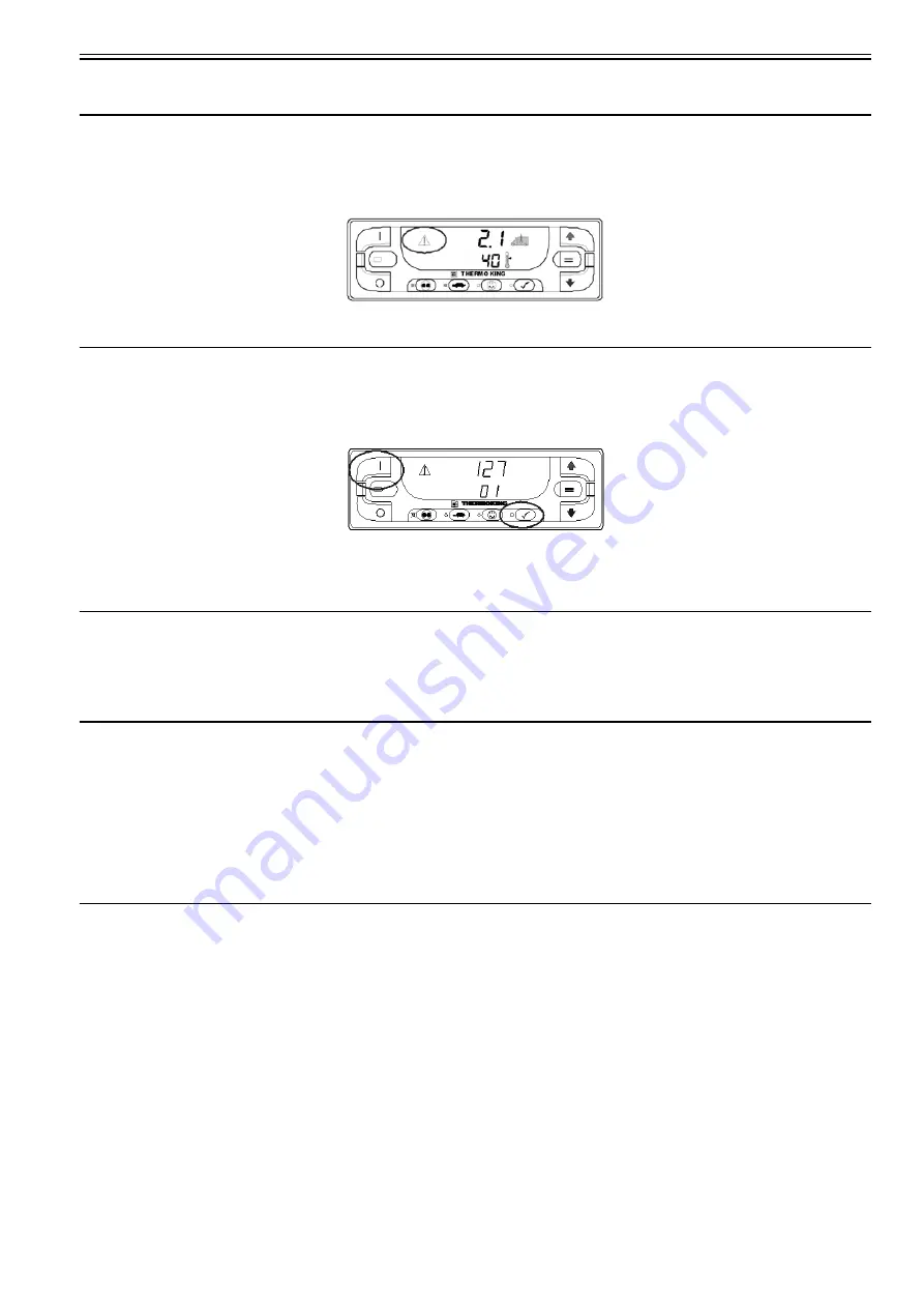
Alarms are displayed by simultaneously pressing and holding the ON Key and PRETRIP TEST Key. The alarm display will
appear as shown below. The upper display shown in Figure indicates that Alarm Code 127 Setpoint Not Entered has been set.
The lower display indicates that only one alarm code exists.
ON and PRETRIP TEST Keys
If more than one alarm code has been set, they are displayed with the most recent alarm shown first. Use the UP ARROW Key
to scroll through the alarms.
Clearing Alarm Codes
After the alarm situation is resolved, press the ENTER Key (See Figure "Standard Display" page 6) to clear the alarm code
currently being shown. When all alarms have been cleared the display will show all zeros to indicate that no alarm codes exist.
The display will return to the Standard Display about 30 seconds after all alarms have been cleared.
Important Alarm Notes
• All alarms must be viewed before any of the alarms can be cleared.
• If an alarm will not clear, it may still exist. If the alarm is not corrected, it will not clear or may be immediately set again.
• Some alarms cannot be cleared using the Standard Truck HMI Control Panel. These alarms must be cleared by maintenance personnel from
the Maintenance or Guarded Access Menus.
• Alarm Code 91 Check Electric Ready Input is cleared by turning the unit off and back on. See SWITCHING FROM ELECTRIC TO
DIESEL in this section.
Refer to the relevant Diagnostic Manual for more information about alarm codes and their diagnosis.
Sending a Servicewatch Data Logger Start of Trip
When the unit is turned on, press and hold the ENTER Key for 5 seconds to send a Start of Trip (SOT) marker to the unit
ServiceWatch Data Logger and the optional DAS Data Logger (if equipped).
Refer to the relevant Diagnostic Manual for more details.
Содержание T-1000R
Страница 14: ...Safety Precautions 2 6 Warning Decals 2e24151g0 ...
Страница 18: ...Specifications 3 4 ENGINE CLUTCH Engagement 600 100 RPM Dynamic Torque 66 fT lb 89 5 N m minimum 1600 RPM ...
Страница 34: ...Maintenance Inspection Schedule 4 10 ...
Страница 57: ...Unit Description 5 23 Purge Mode UT Series 1 3 4 5 2 ...
Страница 67: ...Unit Description 5 33 Zone 1 Cool and Zone 2 Cool UT SPECTRUM Units ...
Страница 69: ...Unit Description 5 35 Purge Mode UT SPECTRUM Units ...
Страница 71: ...Unit Description 5 37 Zone 1 Cool and Zone 2 Heat UT SPECTRUM Units ...
Страница 72: ...Unit Description 5 38 ...
Страница 74: ...Diesel Electric Menu 6 28 Adjust Brightness 6 29 Time 6 30 ...
Страница 120: ...Operating Instructions Standard HMI 7 18 ...
Страница 152: ...Engine Maintenance 9 14 T Series Fuel and Oil System Components TK 376 ...
Страница 154: ...Engine Maintenance 9 16 T Series Fuel and Oil System Components TK 270 ...
Страница 156: ...Engine Maintenance 9 18 UT Series Fuel System Components AMA768 ...
Страница 172: ...Engine Maintenance 9 34 T Series Engine Mounting Components for 2 Cylinder Engine ...
Страница 184: ...Engine Maintenance 9 46 ...
Страница 238: ...Refrigeration Maintenance 10 54 ...
Страница 246: ...Clutch Maintenance 11 8 ...
Страница 258: ...Structural Maintenance 12 12 ...
Страница 264: ...Mechanical Diagnosis 13 6 ...
Страница 265: ...14 Electric Standby Diagnosis ...
Страница 268: ...Electric Standby Diagnosis 14 4 ...
Страница 269: ...15 Refrigeration System Diagnosis ...
Страница 272: ...Refrigeration System Diagnosis 15 4 ...
Страница 280: ...Remote Evaporators 16 8 ...
Страница 282: ...Wiring Diagrams and Wiring Schematics 17 2 ...


