


61
SPECTRUM™ TS Operation
HMI Controller Overview
The HMI (Human Machine Interface) Control
Panel is connected to the microprocessor and is
used to operate the unit. It is located in the truck
cab mounted in or under the dashboard.
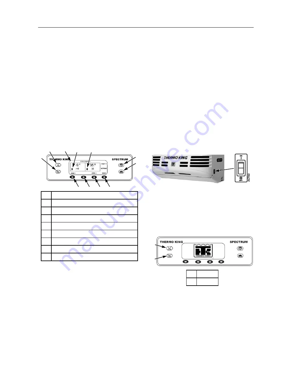
The HMI control panel consists of a display and 8
touch sensitive keys. The display is capable of
showing both text and graphics. The four keys on
the left and right sides of the display are dedicated
keys and the functions are described in detail later
in this chapter. The four keys under the display
are “soft” keys. The function of “soft” keys
change depending on the operation being
performed. If a soft key is active, the current key
function will be shown in the display directly
above the key.
Display
The display is used to supply unit information to
the operator. This information includes setpoint
and temperature for all installed zones, zone
operating information, unit gauge readings,
system temperatures and other information as
selected by the operator.
The Standard Display of box temperature and
setpoint for 2 zones is shown here. In the display
shown here, Zone 1 has a setpoint of -10 F and a
box temperature of -9.4 F. Zone 2 has a setpoint
of 35 F and a box temperature of 35.8 F
Microprocessor Power Switch
The Microprocessor Power switch applies 12 Vdc
power to the microprocessor. The switch must be
in the “On” position to operate the
microprocessor. It is located on the unit frame on
the road side of the unit.
NOTE: When the Microprocessor Power Switch
is turned to the Off position, power is still applied
to the Interface Board and the HMI. To
completely remove power from the control
system, disconnect the unit battery.
Figure 37: Microprocessor Power Switch
Turning the Unit On and Off
The unit is turned on by pressing the
O
N
key and
off by pressing the
O
FF
key. When the On key is
pressed the display will briefly show THERMO
KING as the display initializes.
Then the startup screen shown below appears
while communications are established and the unit
prepares for operation. See Figure 39 on page 62.
1.
On Key (Dedicated Key)
2.
Off Key (Dedicated Key)
3.
Display
4.
Defrost Key (Dedicated Key)
5.
High Speed Lockout Key (Dedicated Key)
6.
Soft Keys
7.
Arrow Up- Zone is Heating
8.
Arrow Down - Zone is Cooling
No Arrow - Zone is in Null
Figure 36: Dedicated and soft keys
AJA1112
6
5
4
2
3
8
1
6
6
6
7
1.
On Key
2.
Off Key
Figure 38: On/Off Key
AJA1167
AJA1107
1
2
Содержание SPECTRUM TS 30 SR NAD
Страница 4: ...4 ...
Страница 10: ...Table of Contents 10 ...
Страница 20: ...Safety Precautions 20 ...
Страница 51: ...Unit Description 51 Figure 19 Front View Figure 20 Back View AJA1350 AJA1500 ...
Страница 52: ...Unit Description 52 1 On Off Switch Figure 21 Side View 1 ...
Страница 60: ...Unit Description 60 ...
Страница 80: ...SPECTRUM TS Operation 80 ...
Страница 90: ...Electrical Maintenance 90 ...
Страница 100: ...Engine Maintenance 100 Figure 130 Early TK 3 95 Fuel and Oil System Components ...
Страница 102: ...Engine Maintenance 102 Figure 131 Late TK 3 95 Fuel and Oil System Components ...
Страница 104: ...Engine Maintenance 104 Figure 132 TK376 Fuel and Oil System Components ...
Страница 136: ...Refrigeration Maintenance 136 ...
Страница 156: ...Hilliard Clutch Maintenance 156 ...
Страница 158: ...Structural Maintenance 158 ...
Страница 168: ...Remote Evaporator Specifications 168 ...
Страница 170: ...Remote Evaporator Maintenance Inspection Schedule 170 ...
Страница 176: ...Remote Evaporator Electrical Maintenance 176 ...
Страница 180: ...Remote Evaporator Refrigeration Service Operations 180 ...
Страница 182: ...Remote Evaporator Structural Maintenance 182 ...
Страница 184: ...Remote Evaporator System Diagnosis 184 ...
Страница 188: ...Wiring and Schematic Diagrams Index 188 ...
Страница 189: ...189 Wiring Diagram Page 1 of 4 ...
Страница 190: ...190 Wiring Diagram Page 2 of 4 ...
Страница 191: ...191 Wiring Diagram Page 3 of 4 ...
Страница 192: ...192 Wiring Diagram Page 4 of 4 ...
Страница 193: ...193 Schematic Diagram Page 1 of 3 ...
Страница 194: ...194 Schematic Diagram Page 2 of 3 ...
Страница 195: ...195 Schematic Diagram Page 3 of 3 ...
Страница 196: ...196 ...


