


Refrigeration Service Operations
118
4. Deburr the hole in the check valve piston bore.
A used drill bit can be modified to use as a
deburring tool.
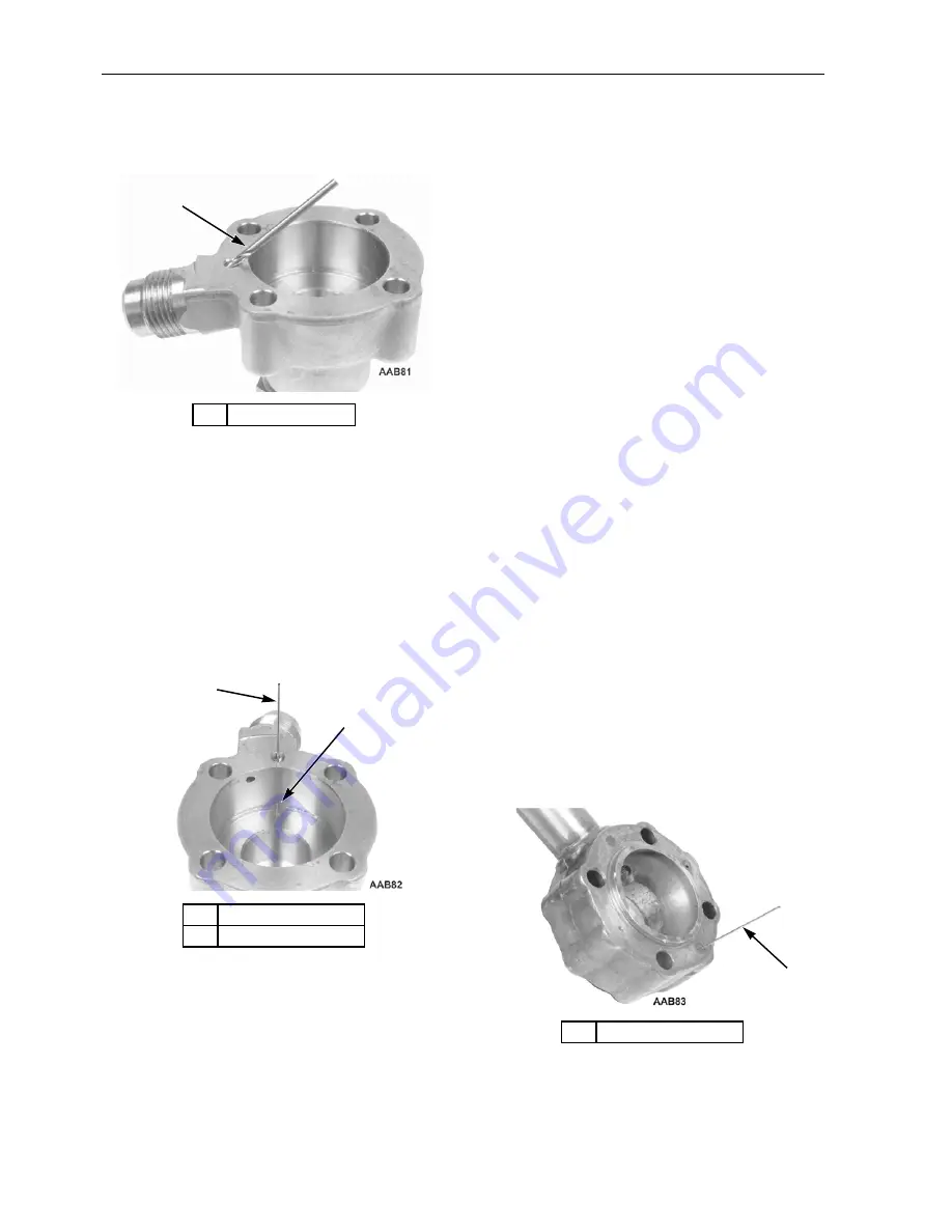
Piston Bleed Orifice Check
1. Use a number 66 (0.033 in. [0.84 mm]) drill
bit to check the orifice in the bleed hole from
the gasket surface to the groove in the bottom
of the piston bore.
2. Carefully check to see that the drill projects
down into the groove and that there are no
burrs at the end of the hole in the groove. Do
not enlarge this hole.
Check Valve Piston Check
1. Reassemble the end cap using a new check
valve piston, spring, stem, and snap ring (Kit
P/N 60-163).
2. Leave the stem back seated against the snap
ring. Use a paper clip bent into a 90 degree
angle to push the check valve piston back in
its bore. Make sure you can feel the piston
working against the spring.
3. With the piston pushed all the way back in its
bore, use a strong light to look down the
0.089 in. (2.26 mm) hole towards the back of
the piston and determine how much of the end
of the hole is covered by the piston. If the
piston covers more than three-quarters of the
hole replace the end cap.
NOTE: When front seating a condenser bypass
check valve DO NOT over-tighten the stem!
Excessive torque will deform the piston and the
deformed piston can increase the hole blockage.
Seat (Center Section) Orifice Check
There are three 0.033 in. (0.84 mm) holes located
in the three-way valve seat (center section). Only
one is used depending on how the valve is config-
ured. If the hole is too large the valve will be slow
to shift from heat to cool when the condenser
pressure is higher than discharge pressure because
gas will flow to the discharge line instead of
behind the piston. If the hole is too small the valve
will be slow to shift from heat to cool when dis-
charge pressure is higher than condenser pressure
because the flow is restricted. Do not enlarge this
hole larger than 0.033 in. (0.84 mm)! Whenever
you disassemble a three-way valve you should
check that all three of the holes are drilled cleanly.
1.
Number 43 Drill
Figure 103: Check Bleed Hole Diameter
1.
Number 66 Drill
2.
Check for Burr Here
Figure 104: Check Piston Bleed Orifice
1
1
2
1.
Number 66 Drill
Figure 105: Check Seat Orifice
1
Содержание SB-210
Страница 4: ...4 ...
Страница 12: ...List of Figures 12 ...
Страница 31: ...Unit Description 31 Unit Photos Figure 6 Front View AJA1617 ...
Страница 32: ...Unit Description 32 1 Defrost Damper 2 X430L Compressor 3 TK 486 Engine Figure 7 Back View 2 3 1 AJA1930 ...
Страница 36: ...Unit Description 36 ...
Страница 49: ...Operating Instructions 49 Figure 32 Viewing Sensors Screen Sequence ...
Страница 54: ...Operating Instructions 54 Figure 40 Datalogger Screen Sequence ...
Страница 101: ...Engine Maintenance 101 ...
Страница 102: ...Engine Maintenance 102 ...
Страница 140: ...Electric Standby Diagnosis 140 ...
Страница 150: ...Index 150 ...
Страница 152: ...Wiring Diagram Index 152 ...
Страница 153: ...153 Model 30 and 50 Schematic Diagram Page 1 of 3 ...
Страница 154: ...154 Model 30 and 50 Schematic Diagram Page 2 of 3 ...
Страница 155: ...155 Model 30 and 50 Schematic Diagram Page 3of 3 ...
Страница 156: ...156 Model 30 and 50 Wiring Diagram Page 1 of 4 ...
Страница 157: ...157 Model 30 and 50 Wiring Diagram Page 2 of 4 ...
Страница 158: ...158 Model 30 and 50 Wiring Diagram Page 3 of 4 ...
Страница 159: ...159 Model 30 and 50 Wiring Diagram Page 4 of 4 ...


