2.9 Offset Calibration
It may be necessary to calibrate the temperature or humidi-
ty controllers to match an independent temperature or humidity
sensor. To do so, follow the next few steps.
1. Suspend an independent, calibrated sensor(s) in the cen-
ter of the interior chamber.
2. Allow approximately 30 minutes for the incubator to
stabilize.
3. Turn off the main power switch.
4. Wear a grounding wrist strap to avoid damaging any of
the electrical components.
Figure 2-5
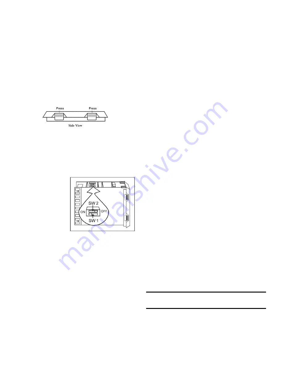
5. Remove the 982 controller module(s) by pressing in the
four retaining tabs, two on the right side, two on the left
side. Refer to Figure 2-5. Pull the controller module out
by gently rocking it from side to side.
6. Looking at the top and right side of the controller mod-
ule, locate the red DIP switches indicated in Figure 2-6.
Use your fingernail
or a small screw-
driver, to turn off
SW 2 by moving
the white toggle
towards the front of
the module as
shown in the illus-
tration.
7. Return the con-
troller into its frame
and firmly press on
the top and bottom of the bezel until all four locking
tabs “click” into place.
8. Turn on the main power switch.
9. Press the Up and Down Arrow keys simultaneously for
3 seconds. The word “InPt” will appear in the upper dis-
play, and “set” will appear in the lower display.
10. Press the Down Arrow once, then continue to press the
Mode key until “LOC” appears in the lower display. The
upper display will show 2. Press the Down Arrow until 0
appears.
11. Press the Mode key once, then the Up Arrow once.
“InPt” will appear in the upper display, and “set” will be
in the lower display. Press the Mode key until “CAL 1”
appears in the lower display. Press the Up or Down
Arrow key to either add or subtract an offset value. This
would be the difference between the actual value shown
on the controller, and the reference sensor value.
12. Press the Display key once.
To turn the hardware lockout back on:
1. Press the Up and Down Arrow keys simultaneously for
3 seconds. The word “InPt” will appear in the upper dis-
play, and “set” will appear in the lower display.
2. Press the Down Arrow once, then continue to press the
Mode key until “LOC” appears in the lower display. The
upper display will show 0. Press the Up Arrow until 2
appears.
3. Press the Display key once.
4. Turn off the main power switch.
5. Wear a grounding wrist strap to avoid damaging any of
the electrical components.
6. Remove the 982 controller module(s) by pressing in the
four retaining tabs, two on the right side, two on the left
side. Pull the controller module out by gently rocking it
from side to side.
7. Looking at the top and right side of the controller mod-
ule, locate the red DIP switches. Use your fingernail or
a small screwdriver, to turn on SW 2 by moving the
white toggle towards the back of the module.
8. Return the controller into its frame and press firmly on
the top and bottom of the bezel until all four locking
tabs “click” into place.
9. Turn on the main power switch.
2.10 Honeywell Recorder (optional)
The Honeywell, DR 4500 Recorder is a one to four-chan-
nel microprocessor-based, circular chart recorder.
The recorder is capable of recording both temperature and
humidity and printing alphanumeric chart data on blank heat-
sensitive chart. Refer to the Honeywell Configuration at the
end of this section and the supplemental Honeywell Recorder
Manual.
2.11 Controller Configuration
The Watlow 982 Temperature and Humidity
Controllers have been configured at the factory. Copies of the
Watlow Configuration records are included on the following
pages.
The controller should not be re-configured without first con-
sulting Thermo Forma Service department at 1-888-213-1790.
Refer to Section 3 of this manual for operating instructions
for the Watlow 982 controllers. The Watlow factory manuals
are included with this manual.
Models 3940 and 3949 ________________________________________________________________Installation and Set-Up
2 - 4
Figure 2-6


