background image

CUTMASTER 40MM


OPERATION 

Manual 0-5084

4T-10

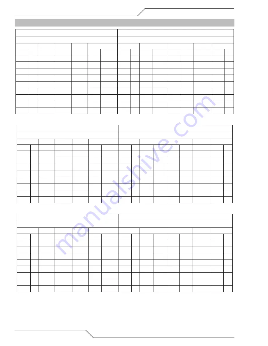
4T.08  Recommended Cutting Speeds for SL100 Torch With Exposed Tip

Type Torch:  SL100 With Exposed Tip

Type Material: Mild Steel

Type Plasma Gas:  Air

Type Secondary Gas:  Single Gas Torch

Thickness

Tip

Output

Amperage Speed (Per Minute)

Standoff

Plasma Gas Press

Flow (CFH)

Pierce

Pierce Height

Inches mm (Cat. No.) Volts(VDC) (Amps)

Inches

Meters

Inches mm

psi*

bar

Plasma Total** Delay (Sec) Inches mm

0.036 0.9 9-8208

104

40

340

8.64

0.19 4.8

65

4.5

55

170

0.00

0.2

5.1

0.06 1.5 9-8208

108

40

250

6.35

0.19 4.8

65

4.5

55

170

0.10

0.2

5.1

0.075 1.9 9-8208

108

40

190

4.83

0.19 4.8

65

4.5

55

170

0.30

0.2

5.1

0.135 3.4 9-8208

110

40

105

2.67

0.19 4.8

65

4.5

55

170

0.40

0.2

5.1

0.188 4.8 9-8208

113

40

60

1.52

0.19 4.8

65

4.5

55

170

0.60

0.2

5.1

0.25 6.4 9-8208

111

40

40

1.02

0.19 4.8

65

4.5

55

170

1.00

0.2

5.1

0.375 9.5 9-8208

124

40

21

0.53

0.19 4.8

65

4.5

55

170

NR

NR

NR

0.500 12.7 9-8208

123

40

11

0.28

0.19 4.8

65

4.5

55

170

NR

NR

NR

0.625 15.9 9-8208

137

40

7

0.18

0.19 4.8

65

4.5

55

170

NR

NR

NR

Type Torch:  SL100 With Exposed Tip

Type Material: Stainless Steel

Type Plasma Gas:  Air

Type Secondary Gas:  Single Gas Torch

Thickness

Tip

Output

Amperage Speed (Per Minute)

Standoff

Plasma Gas Press

Flow (CFH)

Pierce

Pierce Height

Inches mm (Cat. No.) Volts(VDC) (Amps)

Inches

Meters

Inches mm

psi*

bar

Plasma Total** Delay (Sec) Inches mm

0.036 0.9 9-8208

103

40

355

9.02

0.125 3.2

65

4.5

55

170

0.00

0.2

5.1

0.05 1.3 9-8208

98

40

310

7.87

0.125 3.2

65

4.5

55

170

0.00

0.2

5.1

0.06 1.5 9-8208

98

40

240

6.10

0.125 3.2

65

4.5

55

170

0.10

0.2

5.1

0.078 2.0 9-8208

100

40

125

3.18

0.125 3.2

65

4.5

55

170

0.30

0.2

5.1

0.135 3.4 9-8208

120

40

30

0.76

0.187 4.8

65

4.5

55

170

0.40

0.2

5.1

0.188 4.8 9-8208

124

40

20

0.51

0.187 4.8

65

4.5

55

170

0.60

0.2

5.1

0.25 6.4 9-8208

122

40

15

0.38

0.187 4.8

65

4.5

55

170

1.00

0.2

5.1

0.375 9.5 9-8208

126

40

10

0.25

0.187 4.8

65

4.5

55

170

NR

NR

NR

Type Torch:  SL100 With Exposed Tip

Type Material: Aluminum

Type Plasma Gas:  Air

Type Secondary Gas:  Single Gas Torch

Thickness

Tip

Output

Amperage Speed (Per Minute)

Standoff

Plasma Gas Press

Flow (CFH)

Pierce

Pierce Height

Inches mm (Cat. No.) Volts(VDC) (Amps)

Inches

Meters

Inches mm

psi*

bar

Plasma Total** Delay (Sec) Inches mm

0.032 0.8 9-8208

110

40

440

11.18

0.187 4.8

65

4.5

55

170

0.00

0.2

5.1

0.051 1.3 9-8208

109

40

350

8.89

0.187 4.8

65

4.5

55

170

0.10

0.2

5.1

0.064 1.6 9-8208

112

40

250

6.35

0.187 4.8

65

4.5

55

170

0.10

0.2

5.1

0.079 2.0 9-8208

112

40

200

5.08

0.19 4.8

65

4.5

55

170

0.30

0.2

5.1

0.125 3.2 9-8208

118

40

100

2.54

0.19 4.8

65

4.5

55

170

0.40

0.2

5.1

0.188 4.8 9-8208

120

40

98

2.49

0.187 4.8

65

4.5

55

170

0.60

0.2

5.1

0.250 6.4 9-8208

123

40

50

1.27

0.187 4.8

65

4.5

55

170

1.00

0.2

5.1

0.375 9.5 9-8208

134

40

16

0.41

0.187 4.8

65

4.5

55

170

NR

NR

NR

Содержание CutMaster 40MM

Страница 1: ...VictorThermalDynamics com 120 380 400V CUTMASTER 40mm PLASMA CUTTING SYSTEM Operating Manual Revision AK Issue Date February 17 2014 Manual No 0 5084...

Страница 2: ...please take the time to read the entire manual especially the Safety Precautions They will help you to avoid potential hazards that may exist when working with this product YOU ARE IN GOOD COMPANY The...

Страница 3: ...nternational Inc All rights reserved Reproduction of this work in whole or in part without written permission of the publisher is prohibited The publisher does not assume and hereby disclaims any liab...

Страница 4: ...g Specifications 2 3 2 06 Power Supply Features 2 4 SECTION 2 TORCH INTRODUCTION 2T 1 2T 01 Scope of Manual 2T 1 2T 02 General Description 2T 1 2T 03 Specifications 2T 1 2T 04 Options And Accessories...

Страница 5: ...TORCH SERVICE 5T 1 5T 01 General Maintenance 5T 1 5T 02 Inspection and Replacement of Consumable Torch Parts 5T 2 SECTION 6 PARTS LISTS 6 1 6 01 Introduction 6 1 6 02 Ordering Information 6 1 6 03 Po...

Страница 6: ...This Page Intentionally Blank...

Страница 7: ...ma cutting process can be dangerous and hazardous to your health Keep all fumes and gases from the breathing area Keep your head out of the welding fume plume Use an air supplied respirator if ventila...

Страница 8: ...not exceed safe levels For information on how to test for noise see item 1 in Subsection 1 03 Publications in this manual PLASMA ARC RAYS Plasma Arc Rays can injure your eyes and burn your skin The p...

Страница 9: ...American Welding Society Standard AWSF4 1 REC OMMENDED SAFE PRACTICES FOR THE PREPARA TION FOR WELDINGAND CUTTING OF CONTAIN ERSAND PIPING THAT HAVE HELD HAZARDOUS SUBSTANCES obtainable from theAmeri...

Страница 10: ...es informations sur la mani re de tester la fum e et les gaz de votre lieu de travail consultez l article 1 et les documents cit s la page 5 Utilisez un quipement sp cial tel que des tables de coupe d...

Страница 11: ...ection ou une autre sorte de protection oculaire Portez des gants de soudeur et un v tement protec teur appropri pour prot ger votre peau contre les tincelles et les rayons de l arc Maintenez votre ca...

Страница 12: ...s de la American Welding Society 550 N W LeJeune Rd Miami FL 33126 8 Norme 51 de l Association Am ricaine pour la Protection contre les Incendies NFPA LES SYSTEMES GAZ AVEC ALIMENTATION EN OXYGENE PO...

Страница 13: ...10 Electromagnetic compatibility EMC requirements EN 60974 1 2012 Arc Welding Equipment Part 1 Welding power sources Classification The equipment described in this document is Class A and intended fo...

Страница 14: ...ded for industrial use WARNING This ClassAequipment is not intended for use in residential locations where the electrical power is provided by the public low voltage supply system There may be potenti...

Страница 15: ...ranty does not apply to 1 Consumable Parts such as tips electrodes shield cups O rings starter cartridges gas distributors fuses filters 2 Equipment that has been modified by an unauthorized party imp...

Страница 16: ...r All costs associated with lodging the warranty claim including the return of goods to Cigweld or our Nominated Accredited Distributor Accredited Service Provider are the responsibility of the consum...

Страница 17: ...fication numbers Electronic copies of this manual can also be downloaded at no charge in Acrobat PDF format by going to the Victor Thermal Dynamics web site listed below and clicking on Victor Thermal...

Страница 18: ...Duty Cycle N A 40 100 Ratings IEC IEC Current 120 110 DC Voltage 128 124 NOTE The duty cycle will be reduced if the primary input power AC is low or the output voltage DC is higher than shown in this...

Страница 19: ...400 50 23 6 34 31 40 8 10 Line Voltages with Suggested Circuit Protection and Wire Sizes Based on National Electric Code and Canadian Electric Code NOTE Refer to Local and National Codes or local aut...

Страница 20: ...0 5084 2 4 2 06 Power Supply Features Handle and Leads Wrap Torch Leads Receptacle Control Panel Art A 08359 Work Cable and Clamp Art A 08547 Input Power Cord Port for Optional Automation Interface Ca...

Страница 21: ...ingle torch lead provides gas from a single source to be used as both the plasma and secondary gas The air flow is divided inside the torch head Single gas operation provides a smaller sized torch and...

Страница 22: ...eads length Refer to gas pressure settings charts for each model H Direct Contact Hazard For standoff tip the recommended standoff is 3 16 inches 4 7 mm 2T 04 Options And Accessories For options and a...

Страница 23: ...tarter cartridge and out between the tip and shield cup around the plasma arc C Pilot Arc When the torch is started a pilot arc is established between the electrode and cutting tip This pilot arc crea...

Страница 24: ...CUTMASTER 40MM INTRODUCTION Manual 0 5084 2T 4 This Page Intentionally Blank...

Страница 25: ...er Connections CAUTION Check your power source for correct voltage before plugging in or connecting the unit The primary power source fuse and any extension cords used must conform to local electrical...

Страница 26: ...ional air line filter is to be installed 1 Connect the air line to the inlet port The illustra tion shows typical fittings as an example NOTE For a secure seal apply thread sealant to the fitting thre...

Страница 27: ...xample Regulator Input Gas Supply Hose 1 4 NPT to 1 4 6mm Fitting Regulator Filter Assembly 2 Stage Filter Inlet Port IN Outlet Port OUT Two Stage Filter Assembly Art A 07945_AC Hose Clamp Optional Tw...

Страница 28: ...CUTMASTER 40MM INSTALLATION Manual 0 5084 3 4 This Page Intentionally Blank...

Страница 29: ...Do not use tools to secure the connection 1 2 Art A 07885 Connecting the Torch to the Power Supply 3 The system is ready for operation Check Air Quality To test the quality of air 1 Put the ON OFF swi...

Страница 30: ...2 A 02585 Workpiece Square Pinch Block Assembly Mechanical Torch Set Up 3 The proper torch parts shield cup tip start car tridge and electrode must be installed for the type of operation Refer to Sec...

Страница 31: ...ne of the system interlocks is activated 3 ON OFF Power Switch ON OFF Switch controls input power to the power supply Up is ON down is OFF 4 Air Gas Pressure Control The Pressure Control is used in th...

Страница 32: ...main disconnect switch to supply power to the system Air Source Ensure source meets requirements refer to Section 2 Check connections and turn air supply ON Connect Work Cable Clamp the work cable to...

Страница 33: ...O RESTART position when the torch leaves the work piece the pilot arc restarts instantly and the cutting arc restarts instantly when the pilot arc contacts the workpiece Use the Rapid Auto Restart pos...

Страница 34: ...CUTMASTER 40MM OPERATION Manual 0 5084 4 4 This Page Intentionally Blank...

Страница 35: ...t into the torch head until it clicks 4 Install the starter cartridge and desired tip for the operation into the torch head 5 Hand tighten the shield cup assembly until it is seated on the torch head...

Страница 36: ...s life than actual cutting because the pilot arc is directed from the electrode to the tip rather than to a workpiece Whenever possible avoid excessive pilot arc time to improve parts life Torch Stand...

Страница 37: ...be positioned close to the torch head for maximum control or near the back end for maximum heat protection Choose the holding technique that feels most comfortable and allows good control and movemen...

Страница 38: ...conduc tive straight edge to make straight cuts by hand WARNING The straight edge must be non conductive A 03539 Non Conductive Straight Edge Cutting Guide Using Drag Shield Cup With Straight Edge The...

Страница 39: ...pt during drag cutting operations 2 Angle the torch slightly to direct blowback particles away from the torch tip and operator rather than directly back into it until the pierce is complete 3 In a por...

Страница 40: ...e of operation hand or machine torch and the amount of material to be removed Pressure Setting Even though the setting is within the specified range if the torch does not pilot well the pressure may n...

Страница 41: ...ly the leading edge of the arc column produces the cut If the travel speed is too slow a rough cut will be produced as the arc moves from side to side in search of metal for transfer Travel speed also...

Страница 42: ...hield Cup Body 9 8237 Shield Cup 9 8218 Shield Cap Deflector 9 8243 Shield Cup Body 9 8237 Shield Cup 9 8218 Shield Cap Machine 50 60A 9 8238 Drag Shield Cup 9 8235 Drag Shield Cup 70 100A 9 8236 Drag...

Страница 43: ...CUTMASTER 40MM Manual 0 5084 OPERATION 4T 9 This Page Intentionally Blank...

Страница 44: ...mps Inches Meters Inches mm psi bar Plasma Total Delay Sec Inches mm 0 036 0 9 9 8208 103 40 355 9 02 0 125 3 2 65 4 5 55 170 0 00 0 2 5 1 0 05 1 3 9 8208 98 40 310 7 87 0 125 3 2 65 4 5 55 170 0 00 0...

Страница 45: ...hes mm 0 06 1 5 9 8210 119 60 350 8 91 0 19 4 8 70 4 8 90 245 0 00 0 20 5 1 0 075 1 9 9 8210 116 60 300 7 64 0 19 4 8 70 4 8 90 245 0 10 0 20 5 1 0 120 3 0 9 8210 123 60 150 3 82 0 19 4 8 70 4 8 90 24...

Страница 46: ...0 25 6 4 0 120 3 0 9 8211 120 80 300 7 62 0 25 6 4 65 4 5 115 340 0 10 0 25 6 4 0 135 3 4 9 8211 120 80 280 7 11 0 25 6 4 65 4 5 115 340 0 10 0 25 6 4 0 188 4 8 9 8211 120 80 140 3 56 0 25 6 4 65 4 5...

Страница 47: ...8 75 5 2 130 390 NR NR NR Type Torch SL100 with Exposed Tip Type Material Aluminum Type Plasma Gas Air Type Secondary Gas Single Gas Torch Thickness Tip Output Amperage Speed Per Minute Standoff Plasm...

Страница 48: ...1 250 31 8 9 8253 170 120 9 0 23 0 25 6 4 75 5 2 180 360 NR NR NR Type Torch SL100 with Exposed Tip Type Material Aluminum Type Plasma Gas Air Type Secondary Gas Single Gas Torch Thickness Tip Output...

Страница 49: ...ps Inches Meters Inches mm psi bar Plasma Total Delay Sec Inches mm 0 036 0 9 9 8208 109 40 180 4 57 0 125 3 2 65 4 5 55 170 0 00 0 2 5 1 0 05 1 3 9 8208 105 40 165 4 19 0 125 3 2 65 4 5 55 170 0 00 0...

Страница 50: ...s mm 0 06 1 5 9 8210 110 60 165 4 19 0 13 3 2 70 4 8 90 245 0 00 0 20 5 1 0 075 1 9 9 8210 116 60 155 3 94 0 13 3 2 70 4 8 90 245 0 10 0 20 5 1 0 120 3 0 9 8210 115 60 125 3 18 0 13 3 2 70 4 8 90 245...

Страница 51: ...5 1 0 120 3 0 9 8211 115 80 260 6 50 0 125 3 2 65 4 5 115 340 0 10 0 2 5 1 0 135 3 4 9 8211 113 80 250 6 25 0 125 3 2 65 4 5 115 340 0 10 0 2 5 1 0 188 4 8 9 8211 114 80 170 4 25 0 125 3 2 65 4 5 115...

Страница 52: ...0 190 4 8 75 5 2 130 390 NR NR NR Type Torch SL100 With Shielded Tip Type Material Aluminum Type Plasma Gas Air Type Secondary Gas Single Gas Torch Thickness Tip Output Amperage Speed Per Minute Stand...

Страница 53: ...1 250 31 8 9 8253 165 120 10 0 25 0 15 3 8 75 5 2 180 360 NR NR NR Type Torch SL100 With Shielded Tip Type Material Aluminum Type Plasma Gas Air Type Secondary Gas Single Gas Torch Thickness Tip Outpu...

Страница 54: ...US Pat No s 6774336 7145099 6933461 Other Pat s Pending 9 8211 Tip US Pat No s 6774336 7145099 6933461 Other Pat s Pending 9 8212 Tip US Pat No s 6774336 7145099 6933461 Other Pat s Pending 9 8253 Tip...

Страница 55: ...eld Cap US Pat No s 6914211 D496951 Other Pat s Pending The following parts are also licensed under U S Patent No 5 120 930 and 5 132 512 Catalog Description 9 8235 Shield Cap 9 8236 Shield Cap 9 8237...

Страница 56: ...CUTMASTER 40MM OPERATION Manual 0 5084 4T 22 This Page Intentionally Blank...

Страница 57: ...eck of torch tip and electrode Weekly Visually inspect the torch body tip electrode start cartridge and shield cup Visually inspect the cables and leads Replace as needed 3 Months Clean exterior of po...

Страница 58: ...he power supply during cleaning Blowing air into the unit can cause metal particles to interfere with sensitive electrical components and cause damage to the unit 5 03 Common Faults Problem Symptom Co...

Страница 59: ...low the Temp indica tor and 75 psi indicators are on indicating the version would be 2 3 A PSI BAR MAX MAX MIN MIN 1 2 3 4 Art A 07988 MIN MAX 0 1 2 3 4 5 6 7 5 When the Fault indicator is ON or blink...

Страница 60: ...been exceeded 3 Failed components in unit 1 Refer to clearance information section 2 04 2 Allow unit to cool 3 Return to authorized service center for repair or replacement GAS LED OFF FAULT and MIN...

Страница 61: ...uck 3 Worn or faulty torch parts 4 Shorted Torch 5 Temporary Short indicated by 5 blinks per second 6 Power Supply Failure Standard rate of blinking 1 Remove shield cup from torch check upper O Ring p...

Страница 62: ...the lower screws 3 Tighten lower screws 4 Reinstall and tighten the upper screws C Filter Element Assembly Replacement The Filter Element Assembly is in the rear panel For better system performance th...

Страница 63: ...onnect gas supply hose 4 Turn the Filter Housing Cover counter clockwise and remove it The Filter Element is located inside the Housing Art A 02476 Filter Element Cat No 9 7741 Housing Cover Barbed Fi...

Страница 64: ...ment 6 Slide the replacement Filter Elements into the Filter Assembly with the same orientation as noted in Step 4 above 7 Hand tighten the two bolts evenly then torque each bolt to 20 30 in lbs 2 3 3...

Страница 65: ...rch and blowing it through with compressed air CAUTION Dry the torch thoroughly before reinstalling O Ring Lubrication An o ring on the Torch Head andATC Male Connec tor requires lubrication on a sche...

Страница 66: ...e may be an O ring between the shield cup body and drag shield cap Do not lubricate the O ring Drag Shield Cap Shield Cup Body O Ring No 8 3488 Art A 03878 4 Remove the tip Check for excessive wear in...

Страница 67: ...ct your distributor Materials returned without proper authoriza tion will not be accepted 6 02 Ordering Information Order replacement parts by catalog number and complete description of the part or as...

Страница 68: ...50 15 2 m CNC Cable for Automation Interface Kit 9 1011 Art A 02476 Filter Element Cat No 9 7741 Housing Cover Barbed Fitting Spring Assembled Filter O ring Cat No 9 7743 First Second Stage Cartridges...

Страница 69: ...CUTMASTER 40MM Manual 0 5084 PARTS LIST 6 3 7 5 6 3 4 2 Art A 07993_AB 1 8...

Страница 70: ...onnector 4 7853 6 Unshielded Mechanized Leads Assemblies with ATC connectors 1 5 foot 1 5 m Leads Assembly with ATC connector 4 7842 1 10 foot 3 05 m Leads Assembly with ATC connector 4 7843 1 25 foot...

Страница 71: ...CUTMASTER 40MM Manual 0 5084 PARTS LIST 6 5 A 07994_AB 1 4 2 3 5 6 7 8 9 10 12 11 10 13...

Страница 72: ...ads Assemblies with ATC Connectors 1 5 foot 1 5 m Leads Assembly with ATC Connector 4 7846 1 10 foot 3 05 m Leads Assembly with ATC Connector 4 7847 1 25 foot 7 6 m Leads Assembly with ATC Connector 4...

Страница 73: ...Cup Body 9 8237 Shield Cup 9 8218 Shield Cap Deflector 9 8243 Shield Cup Body 9 8237 Shield Cup 9 8218 Shield Cap Machine 50 60A 9 8238 Drag Shield Cup 9 8235 Drag Shield Cup 70 100A 9 8236 Drag Shiel...

Страница 74: ...CUTMASTER 40MM PARTS LIST Manual 0 5084 6 8 This Page Intentionally Blank...

Страница 75: ...lows to set pressure ACTION RUN Rapid Auto Restart SET LATCH switch to RUN for most applications or to Rapid Auto Restart for gouging trimming or expanded metal applications or to LATCH is used for sp...

Страница 76: ...facturer s test procedures Second row Rated cutting current values Third row Conventional load voltage values 4 Sections of the Data Tag may be applied to separate areas of the power supply I Art A 03...

Страница 77: ...Switch 1 Black PIP Negative Plasma 8 Ground ATC Male Connector Front View A 03701 B Mechanized Machine Torch Pin Out Diagram ATC Female Receptacle Front View ATC Male Connector Front View Negative Pl...

Страница 78: ...6 4 3 8 7 1 2 5 6 4 3 8 7 Torch Switch Green White To Power Supply Circuitry B Mechanized Torch Connection Diagram Torch Unshielded Mechanized SL100 Machine Torch Leads Leads with ATC Connector and R...

Страница 79: ...CUTMASTER 40MM Manual 0 5084 APPENDIX A 5 This Page Intentionally Blank...

Страница 80: ...2 35mm A80 C7 C10 may not be installed MTH4 MTH4 TP3 TP3 AC3 AC3 J2 J2 1 2 J9 J9 AC2 AC2 MTH7 MTH7 MOT3 MOT3 C3 C4 C7 C8 C3 C4 C7 C8 SOL 1 SOL 1 MTH6 MTH6 J14 J14 PRI 2 PRI 2 80A_AC2 80A_AC2 J13 J13 1...

Страница 81: ...2 12V1 48V1 I_DMD_1 TIP_SEN COMMON COMMON 12 VDC SUPPLY 48 VDC SUPPLY CURRENT DEMAND TIP DRAG SENSE TEST POINTS J2 J1 CNC PINOUT 1 3 4 7 8 11 12 14 OK TO MOVE PIP START 24VAC RETURN 24VAC SUPPLY OVERT...

Страница 82: ...t section 4T and 6 Updated automation interface and harness descriptions and part numbers per ECOB1282 Feb 25 2010 AD Updated CNC cable part numbers in section 6 per ECOB1637 Sept 14 2010 AE Updated s...

Страница 83: ...This Page Intentionally Blank...

Страница 84: ...ndonesia Customer Care Ph 6221 8990 6095 Fax 6221 8990 6096 Rawang Malaysia Customer Care Ph 603 6092 2988 Fax 603 6092 1085 Melbourne Australia Australia Customer Care Ph 1300 654 674 tollfree Ph 61...

Отзывы: