8
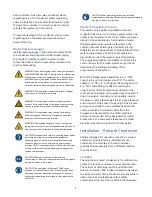
The discharge lines should pitch downward, in the
direction of the hot gas flow, at the rate of ½ inch
per each 10 foot of horizontal run. If the chiller unit
is below the condenser, loop the discharge line to at
least 1 inch above the top of the condenser. Install a
pressure tap valve at the condenser to facilitate
measuring pressure for service. All chillers have
unloading capabilities via compressor unloading;
therefore, they all require a double discharge riser
for proper oil management.
Figure 5 - Double Discharge Riser
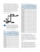
Note: Discharge line sizing for each chiller circuit
capacity is in Table 11. Line sizing shown is listed per
circuit and applies where leaving water temperature
(LWT) is 40°F or higher. For applications where LWT is
below 40°F, size lines using the ASHRAE Refrigeration
Handbook or other suitable design guide.
Table 3 – Horizontal or Downflow Discharge Line
Size
Total
Equivalent
Length (Ft)
Line Size/Circuit (inches OD)
Systems Designed for
20°F to 39°F Set Point
Systems Designed for
40°F to 80°F Set Point
50
Ton
75
Ton
100
Ton
125
Ton
50
Ton
75
Ton
100
Ton
125
Ton
25
2 1/8 2 5/8 2 5/8 3 1/8 2 1/8 2 5/8 2 5/8 3 1/8
50
2 1/8 2 5/8 2 5/8 3 1/8 2 1/8 2 5/8 2 5/8 3 1/8
75
2 1/8 2 5/8 2 5/8 3 1/8 2 1/8 2 5/8 2 5/8 3 1/8
100
2 1/8 2 5/8 2 5/8 3 1/8 2 1/8 2 5/8 3 1/8 3 1/8
125
2 1/8 2 5/8 2 5/8 3 1/8 2 5/8 2 5/8 3 1/8 3 1/8
150
2 1/8 2 5/8 2 5/8 3 1/8 2 5/8 3 1/8 3 1/8 3 5/8
175
2 1/8 2 5/8 2 5/8 3 1/8 2 5/8 3 1/8 3 1/8 3 5/8
200
2 1/8 2 5/8 2 5/8 3 1/8 2 5/8 3 1/8 3 1/8 3 5/8
225
2 1/8 2 5/8 2 5/8 3 1/8 2 5/8 3 1/8 3 1/8 3 5/8
250
2 1/8 2 5/8 2 5/8 3 1/8 2 5/8 3 1/8 3 1/8 3 5/8
275
2 1/8 2 5/8 2 5/8 3 1/8 2 5/8 3 1/8 3 1/8 3 5/8
300
2 1/8 2 5/8 2 5/8 3 1/8 2 5/8 3 1/8 3 1/8 3 5/8
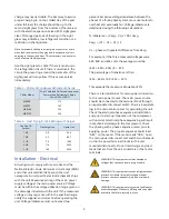
Table 4 – Upflow Discharge Line Size
Total
Equivalent
Length (Ft)
Line Size/Circuit (inches OD)
Systems Designed for
20°F to 39°F Set Point
Systems Designed for
40°F to 80°F Set Point
50
Ton
75
Ton
100
Ton
125
Ton
50
Ton
75
Ton
100
Ton
125
Ton
25
A 1 3/8 1 5/8 1 5/8 1 5/8 1 3/8 1 5/8 1 5/8 2 1/8
B
1 5/8 2 1/8 2 1/8 2 5/8 1 5/8 2 1/8 2 1/8 2 5/8
50
A 1 3/8 1 5/8 1 5/8 1 5/8 1 3/8 1 5/8 1 5/8 2 1/8
B
1 5/8 2 1/8 2 1/8 2 5/8 1 5/8 2 1/8 2 1/8 2 5/8
75
A 1 3/8 1 5/8 1 5/8 1 5/8 1 3/8 1 5/8 1 5/8 2 1/8
B
1 5/8 2 1/8 2 1/8 2 5/8 1 5/8 2 1/8 2 1/8 2 5/8
100
A 1 3/8 1 5/8 1 5/8 1 5/8 1 3/8 1 5/8 1 5/8 2 1/8
B
1 5/8 2 1/8 2 1/8 2 5/8 1 5/8 2 1/8 2 5/8 2 5/8
125
A 1 3/8 1 5/8 1 5/8 1 5/8 1 3/8 1 5/8 1 5/8 2 1/8
B
1 5/8 2 1/8 2 1/8 2 5/8 2 1/8 2 1/8 2 5/8 2 5/8
150
A 1 3/8 1 5/8 1 5/8 1 5/8 1 3/8 1 5/8 1 5/8 2 1/8
B
1 5/8 2 1/8 2 1/8 2 5/8 2 1/8 2 5/8 2 5/8 3 1/8
175
A 1 3/8 1 5/8 1 5/8 1 5/8 1 3/8 1 5/8 1 5/8 2 1/8
B
1 5/8 2 1/8 2 1/8 2 5/8 2 1/8 2 5/8 2 5/8 3 1/8
200
A 1 3/8 1 5/8 1 5/8 1 5/8 1 3/8 1 5/8 1 5/8 2 1/8
B
1 5/8 2 1/8 2 1/8 2 5/8 2 1/8 2 5/8 2 5/8 3 1/8
225
A 1 3/8 1 5/8 1 5/8 1 5/8 1 3/8 1 5/8 1 5/8 2 1/8
B
1 5/8 2 1/8 2 1/8 2 5/8 2 1/8 2 5/8 2 5/8 3 1/8
250
A 1 3/8 1 5/8 1 5/8 1 5/8 1 3/8 1 5/8 1 5/8 2 1/8
B
1 5/8 2 1/8 2 1/8 2 5/8 2 1/8 2 5/8 2 5/8 3 1/8
275
A 1 3/8 1 5/8 1 5/8 1 5/8 1 3/8 1 5/8 1 5/8 2 1/8
B
1 5/8 2 1/8 2 1/8 2 5/8 2 1/8 2 5/8 2 5/8 3 1/8
300
A 1 3/8 1 5/8 1 5/8 1 5/8 1 3/8 1 5/8 1 5/8 2 1/8
B
1 5/8 2 1/8 2 1/8 2 5/8 2 1/8 2 5/8 2 5/8 3 1/8
Calculating Refrigerant Charge
To determine the approximate charge, first refer to
Table 5 and establish the required charge for the
condenser and chiller. Then refer to Table 6 to
determine the charge required for the field-installed
piping per circuit. The approximate charge per circuit
is therefore the sum of the values from Table 5 and
Table 6.
The charge required for an air-cooled condenser
using fan cycling and variable speed for head
pressure control is indeterminate due to site and
environmental variances. Because refrigerant density
increases with decreasing temperatures, the low
ambient operating charge is more (compared to the
summer charge). In the worst case of -20°F, the


