6
the system. This prevents the formation of toxic
gases, corrosive acids, and scale.
CAUTION: Do not use soft solders. For copper-to-
copper joints use a copper-phosphorus braze alloy
(BCuP per the American Welding Society) with 5%
(BCuP-3) to 15% (BCuP-5) silver content. Only use a
high silver content brazing alloy (BAg per AWS) for
copper-to-brass or copper-to-steel joints such as a
45% (BAg-5) silver content. Only use oxy-acetylene
brazing.
Refrigeration Piping Design
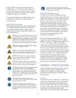
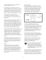
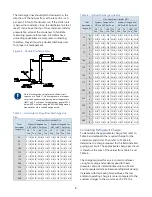
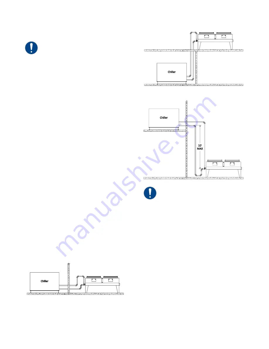
The system is configurable as shown in Figure 1,
Figure 2, and Figure 3. The configuration and its
associated elevation, along with the total distance
between the chiller and the air-cooled condenser,
are important factors in determining the liquid line
and discharge line sizes. This will also affect the field
refrigerant charges. Consequently, it is important to
adhere to certain physical limitations to ensure the
system operates as designed.
General Design Considerations
1.
The total distance between the chiller and the
remote air-cooled condenser must not exceed
200 actual feet or 300 equivalent feet. Keep the
distance as short as possible.
2.
Liquid line risers must not exceed 15 feet in
height from the condenser liquid line
connection.
3.
Discharge line risers cannot exceed an elevation
difference greater than 100 actual feet without a
minimum of 2% efficiency decrease.
4.
To form a proper liquid seal at the condenser,
immediately drop at least 15 inches down from
the liquid outlet before routing the piping to the
chiller. Make the drop leg before any bends or
angles connecting to the remainder of the liquid
connection piping.
Figure 1 – Condenser at Chiller Level
Figure 2 – Condenser Located Above Chiller Unit
Figure 3 - Condenser Located Below Chiller Unit
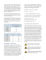
Note: Liquid line sizing for each chiller capacity is in
Table 10. These line sizes are listed per circuit and
apply where leaving water temperature (LWT) is 40°F
or higher. For applications where the LWT is below
40°F, size lines using the ASHRAE Refrigeration
Handbook or other suitable design guide.
Determining Equivalent Line Length
To determine the appropriate size for field installed
liquid and discharge lines, it is first necessary to
establish the equivalent length of pipe for each line.
The equivalent length is the approximate friction loss
from the combined linear run of pipe and the
equivalent feet of elbows, valves, and other
components in the refrigeration piping. The sum
total is the equivalent length of pipe that would have
the same pressure loss. See the ASHRAE
Refrigeration Handbook for more information.
Follow these steps when calculating line size
1.
Start with an initial approximation of equivalent
length by assuming that the equivalent length of
pipe is 1.5 times the actual pipe length.


