


Installation Instructions
English | 13 |
•
Observe all governing codes and ordinances when
grounding. In the absence of these codes or
ordinances observe National Electrical Code ANSI/
NFPA No. 70 current issue. See
recommended grounding method.
•
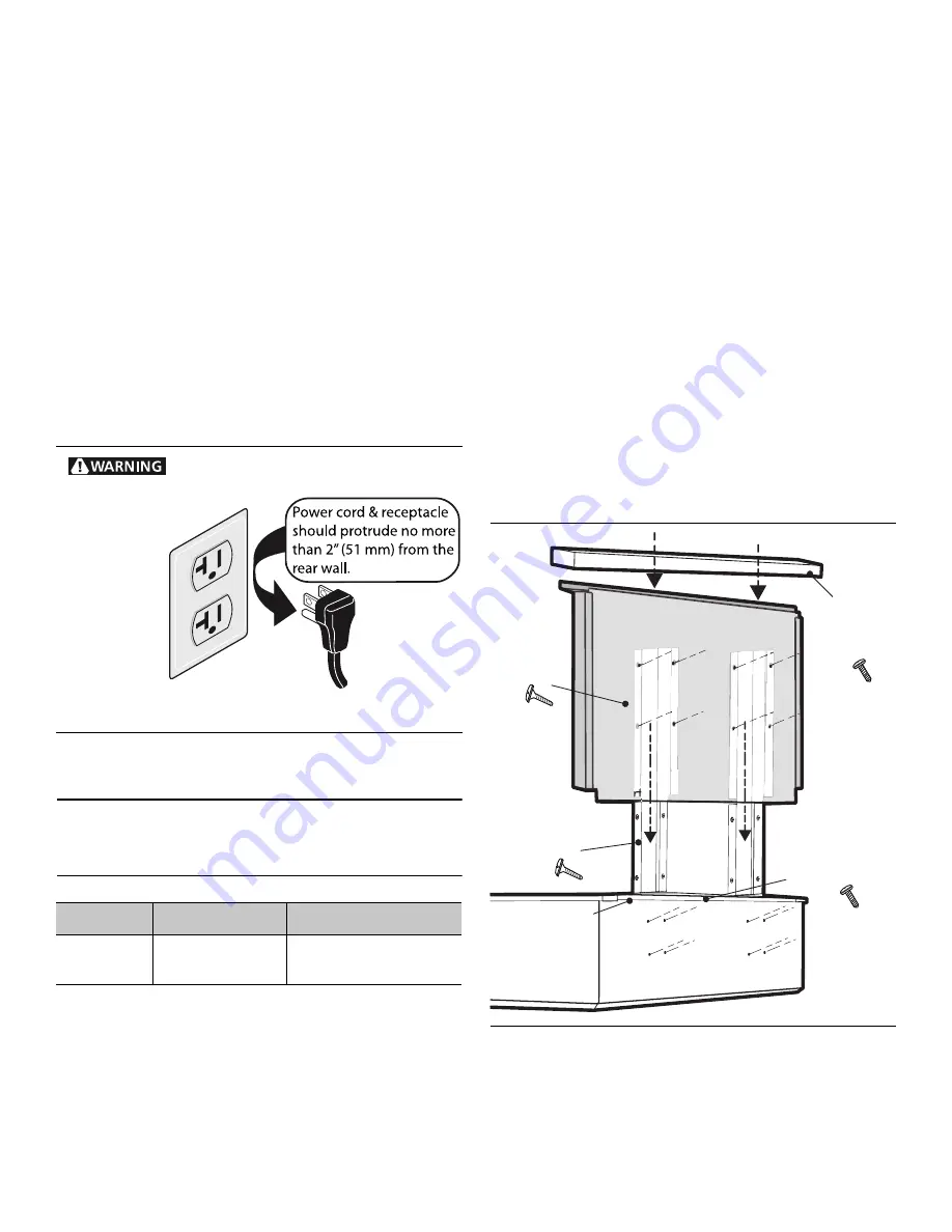
Power cord and receptacle should protrude no more
than 2'' (51 mm) from the rear wall.
•
An electrical wiring diagram and schematic have been
attached to the back of the rangetop chassis for access
by a qualified service technician.
DO NOT
remove or
discard this important information.
•
Installer
- show the owner the location of the circuit
breaker. Mark it for easy reference.
Grounding Method
The rangetop is factory equipped with a power supply cord
with a three-prong grounding plug (with polarized parallel
blades).
STEP 6: Backguard
Installation
For island installations and other installations with over 12''
(305 mm) clearance, the included Flush Island Trim may be
used. A Low Back guard must be installed when there is
less than a 12" (305 mm) clearance between combustible
materials and back edge of rangetop. (See
and
Clearances from non-combustible materials are not part of
the ANSI Z21.1 scope and are not certified by
CSA. Clearances of less than 12'' (305 mm) must be
approved by the local codes and/or by the local authority
having jurisdiction.
Attach the backguard before sliding the appliance into the
final installed position. Follow Steps A through E below:
a. Depending on model, remove the 2 or 3 stainless Torx
screws in the front face of the included Flush Island
Trim. Lift up to fully remove the Flush Island Trim (A,
b. Slide the support brackets between the two rangetop
chassis back panels. Secure each bracket with 4 x 1½''
(38 mm) screws (B,
c. Slide backguard over the two brackets on the rear of
the rangetop. Fasten them together with 8 x 1½''
(38 mm) screws (C,
d. Fasten the front of the backguard to the rangetop with
2 or 3 x ½'' (12.7 mm) screws (D,
e. Place the backguard cap on top and secure using 2 x
½'' (12.7 mm) stainless screws (E,
Figure 11: Recommended Grounding Method
Rangetop
12'' Low Back
Flush Island Trim
36''
48''
PA36GLBC
PA48GLBC
Included with rangetop
Included with rangetop
This product must be properly grounded.
NOTE: Plug styles may vary.
Figure 12: Low Back Attachment
c.) Slide backguard
over support brackets
& secure with 8 x
1½" (38 mm) screws
c.) Slide backguard
over support brackets
& secure with 8 x
1½" (38 mm) screws
c.) Slide backguard
over support brackets
& secure with 8 x
1½" (38 mm) screws
e.) Fasten cap
with 2 x ½"
(12.7 mm)
screws
e.) Fasten cap
with 2 x ½"
(12.7 mm)
screws
e.) Fasten cap
with 2 x ½"
(12.7 mm)
screws
d.) Secure front
with ½" (12.7 mm)
stainless screws
a.) Remove Trim
a.) Remove Trim
a.) Remove Trim
b.) Install support
brackets with 8
x
1½" (38 mm)
screws
b.) Install support
brackets with 8
x 1½" (38 mm)
screws
b.) Install support
brackets with 8
x 1½" (38 mm)
screws
Содержание PCG364GD
Страница 1: ...THERMADOR PROFESSIONAL RANGETOPS ...