17
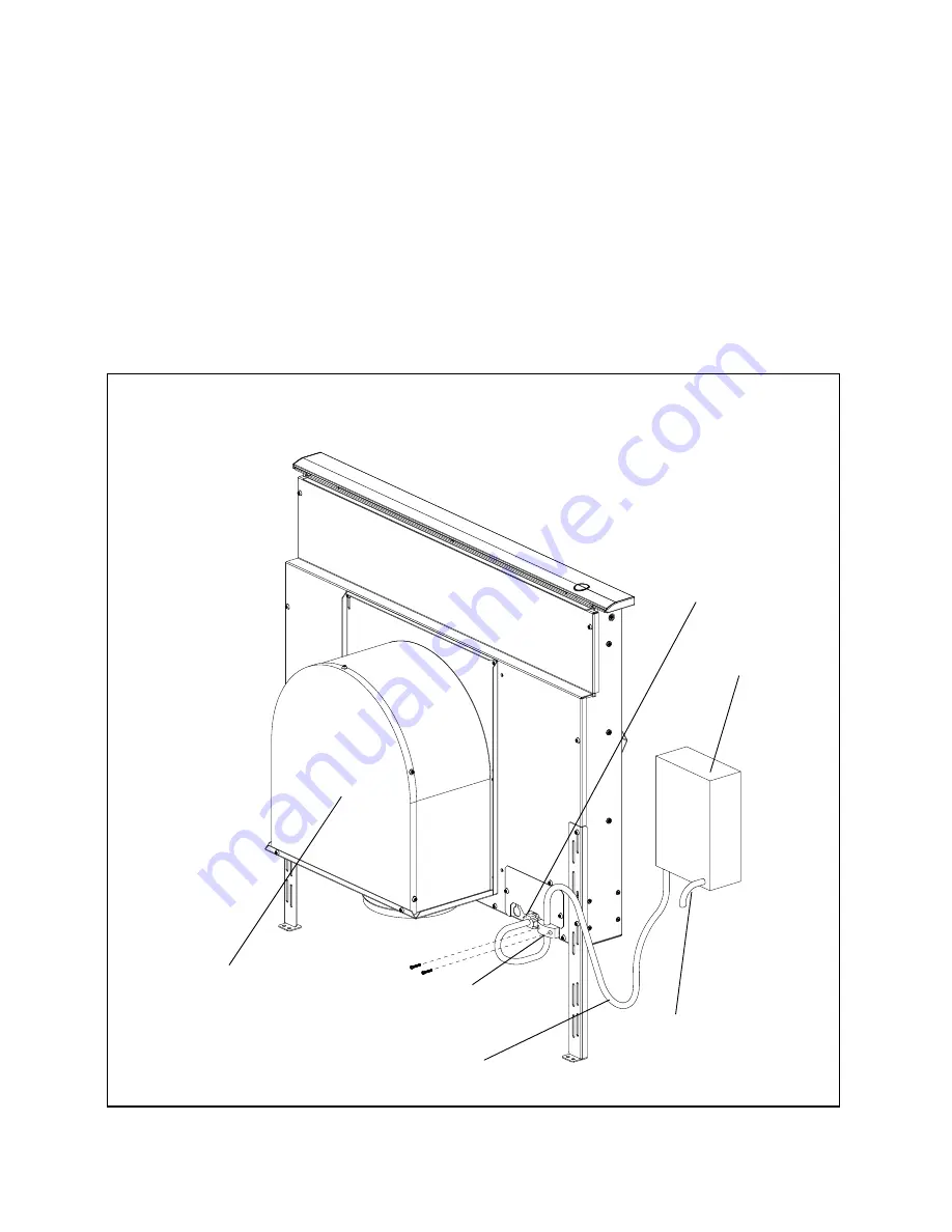
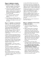
Remote Blower VTR600R or VTR1000Q
(see Figures 11 and 12 for further detail):
A. Remove junction box cover and connect
conduit with 5 wires from remote blower.
Hook up wires per Wiring Diagramm.
Fig. 10. Replace junction box cover.
B. Attach duct transition Model CV2T6 at
mounting holes with sheetmetal screws.
C. Feed remote blower pigtail through strain
relief.
D. Attach strain relief to downdraft near
junction box.
Integral Blower VTN600CV2C
(see Figures
10 and 12 for further detail):
E. Connect pigtail to downdraft at 6 pin
connector.
F. Run pigtail wires to juntion box.
G. Inside junction box, connect conduit with
five wires from remote blower. Use a
conduit connector to secure.
Note:
Blower and duct transition box may
be installed with duct outlet left, down or
right. Install blower or duct transition in
such a way that access panels can be
removed for service.
S
tr
a
in
Re
li
e
f
J
un
c
tion
B
ox
C
on
d
uit
T
o
Re
mot
e
B
low
e
r
F
igure 11 - Remote
B
lower
T
r
a
nsition
C
V
2
T
6
Re
mot
e
B
low
e
r
P
igt
a
il
6
P
in
C
onn
ec
tor
Fig. 11 – Remote Blower
Содержание CVS2 Series
Страница 1: ......
Страница 2: ...2 en page 03 19 fr page 20 36 es página 37 53 ...
Страница 54: ...54 Notes ...
Страница 55: ...55 Noticias ...


