1-877-420-1330
Quest DRY 180 Installation, Operation and Maintenance Instructions
5
www.QuestHydro.com
quest
quest
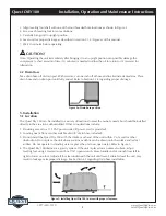
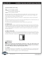
3. Align leveling foot shaft with one of the four threaded hole locations as shown in Figure 2.
4. Screw each leveling foot in ten revolutions.
5. Carefully bring unit to upright position.
6. Level unit for proper drainage as described in section 5.1.4 (Figure 6) of this manual.
7. Wait 10 minutes before operating.
Note: Operating the unit immediately after bringing it to an upright position can possibly damage the
compressor. A short amount of time (10 minutes) is needed to allow the oil to return to it’s reservoir for
lubrication.
4.2 Drain Hose
T
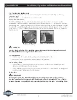
ake drain hose off of drain port. With scissors, cut one inch off of hose end to eliminate dented area. Place
drain hose end on drain port until fully seated. Refer to Section 5.1.4 regarding proper drainage.
5. Installation
5.1 Location
The Quest Dry 180 can be installed in a variety oflocations to meet the owner’s needs, but should beinstalled
directly in the area to be dehumidified. Other considerations include:
1. Providing access to a 115 VAC power outlet (8’ power cord is provided).
2. Locating near a floor or other suitable drain (8’ drain hose included).
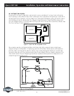
3. Do not install the Quest Dry 180 with the intake or exhaust of the unit within 1’ of a wall or other
obstruction. Do not place the unit where curtains or debris can be drawn onto the intake and restrict
airflow. Do not operate in standing water or place the unit near open water. Refer to Figure 5.
4. The Quest Dry 180 drains via a gravity system. If the unit is placed on an unlevel surface, adjust
leveling feet using a crescent wrench or 7/16” open wrench. Move handle end of wrench from left to
right to lower one foot. Adjust all four feet underneath the unit until level. Failure to level the unit may
result in leakage or improper drainage. See Section 4.2 regarding drain hose installation.
CAUTION!
Figure 2a: Drain hose position
Figure 5: Installing Quest Dry 180 in area with proper clearance.


