


ECHO PELLET E.I. II
PELLET HEATER
12
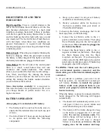
9. The pellet heater must be operated with a power
source and will not operate using natural draft.
If there is a power failure the heater will shut
down. If the 12-volt back-up system is installed,
the heater will automatically switch to the 12-
volt power.
Route the power supply cord so it does not
touch any of the exterior components of the
heater.
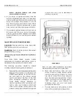
a. When exiting through the wall with your
Type "L" pellet vent pipe, you may go
straight out through a wall thimble. You
must connect a pellet vent tee at this point
and extend the vent pipe at least 5 feet
vertically outside to provide good draft and
allow the gases to exit. The tee must have a
clean out cap for inspection and regular
cleaning (see Figure 4). Whenever the pipe
run in any installation is 10 feet or more, the
use of 4-inch Type "L" vent pipe is required.
Horizontal runs must be limited to 2 feet. A
wall band is required for every 4 feet
minimum on a vertical run at an exterior
wall.
b. All pellet vent pipe connections including
exit at the rear of the heater should be
secured with three screws and sealed with
high temperature silicone (450 degrees) or
metallic duct tape. This prevents smoke and
soot leakage into the living area. If this is
not done, there is a possibility that the room
fan will pick up any leakage and blow it into
the room. This requirement is waived if the
new Dura Vent Pellet Pro pipe is used.
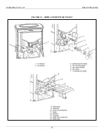
c. Installation per Figure 7 requir
es 4” pel
let pipe.
10. Outside Air Hook-up: Thelin Hearth Products
recommends using a Dura Vent Wall Thimble
with a built-in outside air hook-up and flex
tubing.
FIGURE 7
Содержание ECHO-COMSTOCK PELLET E.I. II
Страница 4: ...ECHO PELLET E I II PELLET HEATER 4 LABORATORY LISTING LABEL...
Страница 9: ...ECHO PELLET E I II PELLET HEATER 9 FIGURE 4...
Страница 10: ...ECHO PELLET E I II PELLET HEATER 10 FIGURE 5...
Страница 11: ...ECHO PELLET E I II PELLET HEATER 11 FIGURE 6...
Страница 14: ...ECHO PELLET E I II PELLET HEATER 14 FIGURE 8...
Страница 22: ...ECHO PELLET E I II PELLET HEATER 22 FIGURE 13 REPLACEMENT PARTS LIST...
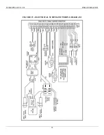
Страница 24: ...ECHO PELLET E I II PELLET HEATER 24 FIGURE 15 ELECTRICAL SCHEMATIC WIRING DIAGRAM 250 VAC 250 VAC...
Страница 27: ...ECHO PELLET E I II PELLET HEATER 27 APPENDIX B E I FIREPOT ASSEMBLY...
Страница 29: ...ECHO PELLET E I II PELLET HEATER 29 APPENDIX D IGNITER REMOVAL...
Страница 31: ...ECHO PELLET E I II PELLET HEATER 775 241 2586...


