


3)
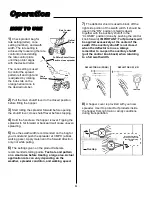
Periodically grease the axle
bearing housings as indicated in
assembly step #10. Turn the
spreader up side down and
apply a few drops of oil to the
impeller shaft bearing as shown
and allow oil to penetrate
bearing.
Assembly
continued
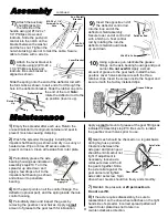
Insert the opposite end of
the deflector control rod
into the loop end of the
deflector shield assembly.
Secure lower end of control rod
with a hitch pin. Test control
rod by rotating the rod–the
deflector shield should rotate
up and down.
Maintenance
Grease Fittings
3
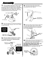
Attach the auxiliary
shutoff bracket to
the left side of the
handle using (2) #10
-
24 x 1
1/4”
Phillips screws and
locknuts. Slide the push
-
pull
control into the notch on the
bracket between the washer
and the hex nut. Tighten the
nut while taking care not to twist the cable. Secure
cable to frame with a wire tie.
7)
Attach the lever bracket to
handle using (2) #10
-
24 x
1 1/4”
Phillips screws and
locknuts. Be sure bracket is
aligned as shown.
8)
Slide the spring onto the end of the deflector rod with
the form tabs as shown. Insert end of rod through the
hole in the deflector bracket. Slide the rubber cap onto
the end of the rod.
Note:
rotate the deflector rod to the
up position (lever is up).
9)
Using a grease gun, lubricate the grease
fittings on the axle bearing housings and gear
carrier.
Do not overfill.
Apply a small
amount of grease to the gear teeth. Install the two
gearbox cover halves and secure with the three
retainer clips. Insert the screen inside the hopper and
secure it with the factory installed clips.
10)
1)
Empty the spreader after each use. Return the
unused material to its original container and seal to
prevent moisture
-
causing clumping.
2)
Wash the spreader thoroughly including the
impeller shaft bearing as shown and dry in a sunny or
heated area. Wipe or blow off excess water to
prevent corrosion. Clean all residue from rotor plate.
4)
Oil the pivot points on all the control linkage, the
deflector (optional part), and the spring inside the rate
control housing.
5)
Periodically clean and inspect the gears by
removing the gearbox cover halves. Apply a
small
amount of grease to the gear teeth for lubrication.
Wash Bearing &
Apply Oil
Apply a
small
amount of grease at the gear fittings as
indicated is assembly step #10. Be sure to reinstall
the gearbox cover halves prior to use.
6)
Gear mesh should be checked on a regular basis
during high use periods.
Clearance between the
axle gear and pinion gear
should be minimal but not
tight. If adjustment is
necessary, loosen axle
collar set screw and hold
the gears together. Slide
the axle collar against the
gear carrier and tighten
axle collar set screw. Spin
drive wheel. Gears should run freely and smoothly.
Grease
Gear Carrier
Axle Collar
7)
Maintain tire pressure at
20 psi maximum
.
Do not overfill.
8)
If the axle requires disassembly, be sure to
reassemble it so the drive wheel attaches on the right
hand side of spreader. Incorrect spread pattern will
result if rotor plate does not rotate in a
counter
-
clockwise direction.
Aux. Shutoff
Bracket
Grease Fittings
Push
-
Pull
Control
#10
-
24 x 1
1/4”
Screws & Lock
Nuts
Lever Bracket
Spring
Deflector Rod
Cap
Deflector Rod
Hitch Pin Cotter
Rotate Rod
Up


