background image

GVIS 300 • GVIS 400 • GPAD 250

Greenlee / A Textron Company

4455 Boeing Dr. • Rockford, IL 61109-2988 USA • 815-397-7070

17

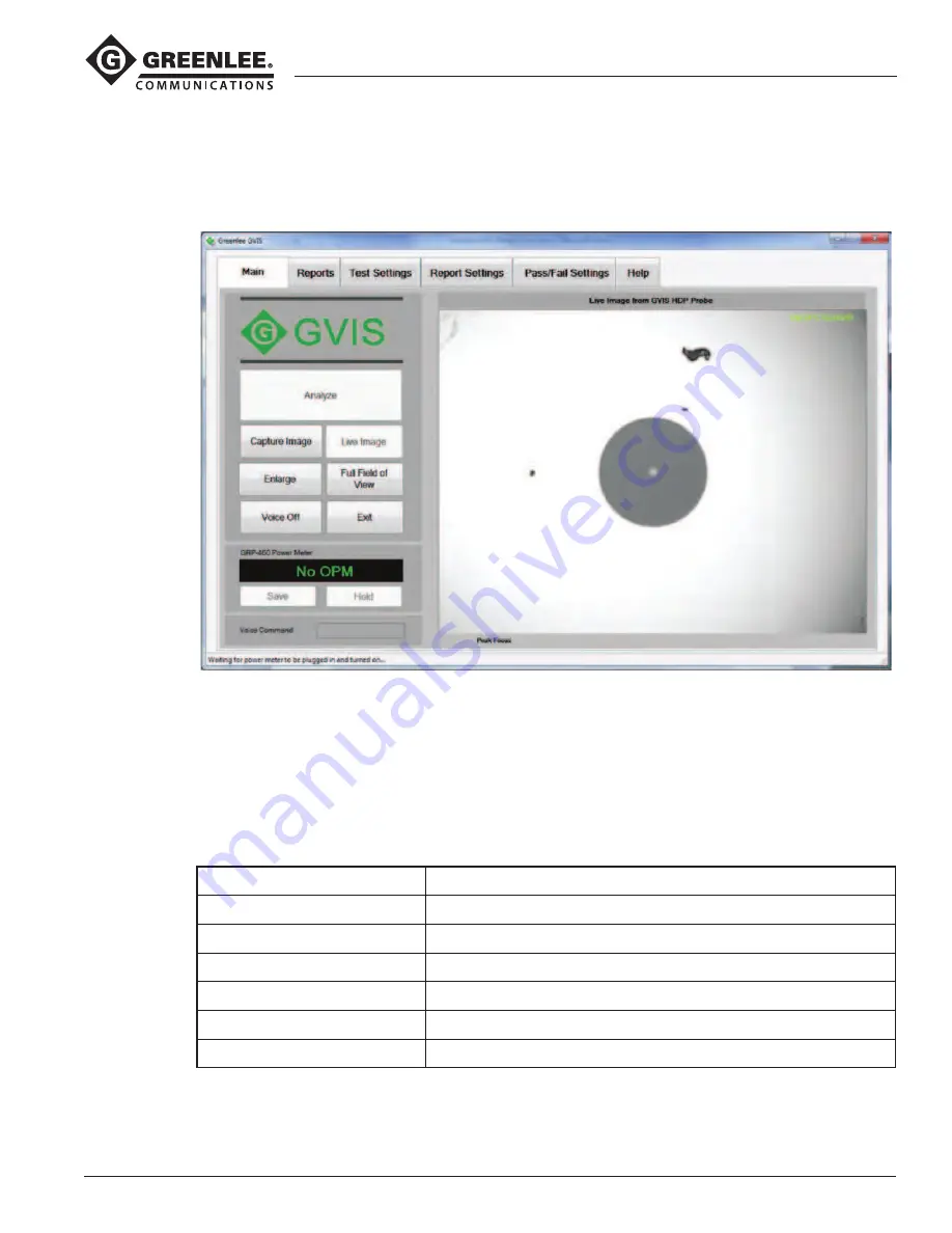
Magnify and Center

Click the 

Magnify and Center 

button to magnify the image displayed approximately 2.5 times and to center the 

fiber end face. See Figure 8.
To return to the normal view, click the 

Full Field of View 

button.

Figure 8. Magnify and Center Screen

Voice On/Off

Voice commands can be used in situations when both hands are busy. Voice commands can be turned on and 
off by clicking the 

Voice Commands 

button. When on, command feedback is given as illustrated in Figure 9. 

When green, the command was understood. When yellow, a command was understood but may have been 
misinterpreted. Red indicates the command was not understood.
Below are a few voice commands that can be used rather than clicking on a button.

Button

Voice Command

Capture Image

“Capture Image” or “Cheese”

Hold/Read*

“Hold” or “Read”

Save/Measure*

“Save” or “Measure”

Magnify & Center*

“Center Image” or “Full View”

Analyze

“Analyze”

Voice Commands On

“Disable Voice”

* For these commands you can use the same command to toggle between button states. For example, when 

you say “Center Image”, GVIS magnifies and centers the image. Rather than saying “Full View”, you can say 

“Center Image” again to return back to full view.

Содержание GREENLEE GPAD 250

Страница 1: ...safety information in this manual before operating or servicing this tool Register this product at www greenlee com 52069973 REV 2 2015 Greenlee Textron Inc 10 15 GVIS 300 Video Inspection Scope GVIS 400 Video Inspection Scope GPAD 250 Portable Access Device Español 33 ...

Страница 2: ...l 2 5 mm tip and a SC bulkhead adapter Optional adapters for most commonly used connectors are available Safety Safety is essential in the use and maintenance of Greenlee tools and equipment This instruction manual and any mark ings on the tool provide information for avoiding hazards and unsafe practices related to the use of this tool Observe all of the safety information provided Purpose of thi...

Страница 3: ...harger than the only supplied Failure to observe these precautions may result in injury or property damage Contents GVIS 300 GVIS 300 monitor housed in a protective nylon padded pouch GVIS 300 probe with 2 5 mm universal connector tip attached AC charger for GVIS monitor 2 5 mm universal connector adapter tip SC bulkhead adapter tip Pen and square cleaning kit USB cable Hard carry case Instruction...

Страница 4: ... care of the optical interface at the tip of the probe GVIS 300 Monitor 4 Display Case The display case includes the 3 5 inch LCD display battery and control features to display the required image No user serviceable components are found inside 5 Conn Probe This control button is for possible future functionality only If the button is inadvertently pushed push it again so that the display toggles ...

Страница 5: ...hotspot 3 Power Switch Used to turn the GPAD 250 on and off so that a Wi Fi hotspot is activated 4 Power Connection To charge the battery insert the AC charger into this connector Total run time using the battery is approximately 4 hours The battery can be re charged while the hotspot is active but the re charge will take longer 5 Fan Regulates the internal temperature of the GPAD 250 To prevent o...

Страница 6: ...19 mm Weight probe case and tips 1 2 lb 0 54 kg GPAD 250 Wi Fi Connectivity 802 11 abgn Wi Fi access point Battery 11 1 V lithium ion Battery Life 4 hours Battery Charger AC wall pack 12 6 V lithium ion Communication Distance 200 60 m GPAD 250 to wireless device Dimensions 4 5 L x 1 5 W x 2 75 H 114 mm x 38 mm x 70 mm Weight 0 5 lb 0 25 kg Accessories GVIS 300 and GVIS 400 Connector Adapters GAC 0...

Страница 7: ...sed in a padded protec tive nylon case Although this case provides field abuse pro tection the GVIS 300 display must be protected from direct impact Should the display need surface cleaning optical grade cleaning solutions and tissues may be used GVIS 300 Battery Maintenance The GVIS 300 includes a rechargeable lithium ion battery capable of powering the unit for more than 8 hours of continu ous u...

Страница 8: ...GVIS 300 GVIS 400 GPAD 250 Greenlee A Textron Company 4455 Boeing Dr Rockford IL 61109 2988 USA 815 397 7070 8 ...

Страница 9: ...Windows 7 Windows 8 Software Requirements Microsoft NET Framework 4 or newer Microsoft Visual C 2010 x86 Redistributable Windows Driver Requirements Imager Support GVIS 400 HDP uses the UVC 1 1 driver included with Windows no other driver installation is needed GVIS 300 uses the Videology driver Serial Port Support If Greenlee s GRP 460 power meter is to be used download the FTDI serial port drive...

Страница 10: ...tion package and double click on SetupVid and follow the installation instructions If there is no C after the serial number then go to web page http www videologyinc com download htm and download the SFT 04040 Windows driver and follow the installation instructions Connecting Greenlee Devices to Your PC GVIS 400 HDP Connect the Greenlee GVIS 400 HDP cable to the PC s USB port Wait for Windows to l...

Страница 11: ...ndly and supports screen rotation to make it more convenient when used with tablets Figure 1 illustrates the main screen in the landscape mode Figure 2 illustrates the main screen in the portrait mode In this manual all subsequent figures are illustrated in the landscape mode but the operation of GVIS is the same in the portrait mode Only the button sizes and locations are changed to accommodate t...

Страница 12: ...nts GVIS 400 HDP Visual Inspection Scope Plug the GVIS 400 HDP into a USB port of the PC Power is supplied by the USB port GVIS 300 Visual Inspection Scope Using the supplied USB cable plug the GVIS 300 into a USB port on the PC Apply power to the device GRP 460 Optical Power Meter Using the supplied USB cable plug the GRP 460 into a USB port of the PC Apply power to the device Starting GVIS Run G...

Страница 13: ...eports the analysis by comparing defects to the IEC 61300 3 35 2009 specification See Automatic Analysis in the Performing a Test section for more information A GVIS 400 HDP or GVIS 300 can be used for the manual graded method For manual grading the technician connects the fiber to the probe focuses the image and grades the fiber end by visually inspecting the image See Manual Grading in the Perfo...

Страница 14: ...e 1 Tab selection 2 PASS FAIL indicator 3 Live or Saved Image display window 4 Status bar 5 Optical power meter GRP 460 control and measurement 6 Grading circles 7 Pass Fail buttons 8 Hide Show grading 9 Sample obstruction overlay circles Tool Tips Hold the cursor over a button to display a tool tip describing its function See Figure 5 Figure 5 Tool Tips ...

Страница 15: ...s focused Capture Image When a live image is displayed in the image window the Capture Image button is enabled on the Main tab Click on Capture Image to open the Save File window Here you can create a new folder to save the image or save it in an existing folder When a fiber end image is saved the information under the Report Settings tab Customer Company Name for example is saved as well Click on...

Страница 16: ...988 USA 815 397 7070 16 Enlarge Click the Enlarge button to display a larger version of the image displayed on the main screen as shown in Figure 7 Click the Windows X button in the upper right corner or click the Exit button to close the Enlarge image window Figure 7 Enlarged Image Window ...

Страница 17: ...on command feedback is given as illustrated in Figure 9 When green the command was understood When yellow a command was understood but may have been misinterpreted Red indicates the command was not understood Below are a few voice commands that can be used rather than clicking on a button Button Voice Command Capture Image Capture Image or Cheese Hold Read Hold or Read Save Measure Save or Measure...

Страница 18: ...mage When the focus ring on the Greenlee probe is rotated and the image becomes more focused the red peak bar stays at the best focus achieved Each time a new peak is reached the image associated with the peak is saved in a temporary buffer If the image becomes unfocused again after a peak is reached the peak focused image is still saved When the Analyze button is pressed the best focused image is...

Страница 19: ...Textron Company 4455 Boeing Dr Rockford IL 61109 2988 USA 815 397 7070 19 Figure 10 Unfocused Fiber End Figure 11 Focused Fiber End Figure 12 A Focused Image Is Needed to Perform a Successful Automated Analysis Exit Click Exit to close GVIS ...

Страница 20: ...gure 13 Reports Tab GVIS Report Button To create a GVIS report select one or two fiber end images and click GVIS Report Power Measurements To include power measurements in a report first select one or two images that you would like to associate with the power measurement Then click the Save button on the Main tab when an appropriate loss measurement is displayed Site Loss Report Button Creates an ...

Страница 21: ... mode is not available if a GVIS 300 is selected for a video source Fiber Type The two types of fiber the technician may choose are single mode and multi mode So that the correct size critical zone is used during analysis the technician must choose the correct fiber type Single mode diameter is 25 μm multi mode is 65 μm Choosing a Video Source To select a video source click on the drop down box in...

Страница 22: ...age brightness contrast sharpness and gamma using these controls Figure 15 Image Controls IEC Profile 61300 3 35 When performing a test using automatic analysis you have to choose the IEC specification to compare defect sizes and locations The specification is used to determine whether the end face passes or fails the test The test choices are Single mode UPC 45 dB Multi mode PC Single mode APC Si...

Страница 23: ...ted These lists can be added to by clicking the Add button next to the item These are labeled Customer Company Name Contact Name Testing Company Name Tester s Name and Test Location To delete an item from a list select the item and press the Del button next to the item Text boxes labeled Fibers From Fibers To and Comment can be updated to reflect your test location On the top header portion of the...

Страница 24: ...Tab Loss measurement pass fail limits can be set and enabled on this tab as shown in Figure 17 If enabled and the power meter measurement exceeds the set limit the measurement is marked as Fail on the reports Help Tab The Help tab contains the GVIS version number and software manual It also contains user specific guides and end face zone details Figure 18 Help Tab ...

Страница 25: ...rger than the specified size and cause a failure See IEC 61300 3 35 2009 specification for detailed information To show detailed information about a defect mouse over the defect so that a pop up window appears below the Pass Fail box in the upper left hand corner See Figure 19 To change the specification that is used to determine pass or fail choose Test Settings tab and choose the desired specifi...

Страница 26: ...button If no grading is desired press the None button Figure 21 None Pass Fail and Show Hide Buttons The grading circles can be centered on the fiber core by pointing the mouse at core center and right clicking or by clicking the Locate button They also can be nudged left right up or down by first clicking the fiber image then using the arrow keys on the keyboard Press and hold the Shift key and p...

Страница 27: ...GVIS 300 GVIS 400 GPAD 250 Greenlee A Textron Company 4455 Boeing Dr Rockford IL 61109 2988 USA 815 397 7070 27 Figure 22 Grading Circles Displayed Figure 23 Grading Circles and Pass or Fail Displayed ...

Страница 28: ...pted by the screen in Figure 25 Hint Press and hold the Shift key and click the image if you want to select two images Figure 24 Two Fiber End Images Selected to Save Power Measurements to those Images Loss Measurement Prompt The Loss Measurement prompt assists in saving the power meter measurement for reports When you choose No in Figure 25 you are indicating the measurement is just for the trunk...

Страница 29: ...e your reports will not be accurate Increment Automatically Check this if you want the location number to increment by one every time you make a measurement and save it to an image file Reset Resets the Location Number to 1 Always Just Trunk Check this if your measurements are always trunk and do not include the top sector If checked you will not be prompted for top sector measurements as shown in...

Страница 30: ...r meter measurements for the selected test The Site Loss Report information includes all the tests for the folder selected and displayed at the bottom of the GVIS screen Figures 28 and 29 illustrate these reports GVIS Report Click on the GVIS Report button to display results similar to the figure below To display the results you must first select one or two images in the image list before clicking...

Страница 31: ...70 31 Site Loss Report If you have Microsoft Excel installed on your computer click on the Site Loss Report button to create a site loss report of all the optical power measurements made that are associated with the end face images presently displayed in the selected folder Figure 29 Excel Site Loss Report ...

Страница 32: ...88 USA 815 397 7070 An ISO 9001 Company Greenlee Textron Inc is a subsidiary of Textron Inc USA Tel 800 435 0786 Fax 800 451 2632 Canada Tel 800 435 0786 Fax 800 524 2853 International Tel 1 815 397 7070 Fax 1 815 397 9247 www greenlee com ...

Страница 33: ...ad de este manual antes de usar esta herramienta o realizar su mantenimiento Registre este producto en www greenlee com 52069973 REV 2 2015 Greenlee Textron Inc 10 15 Boroscopio de inspección de video GVIS 300 Boroscopio de inspección de video GVIS 400 Dispositivo de acceso portátil GPAD 250 ...

Страница 34: ...d La seguridad es esencial en el uso y mantenimiento de herramientas y equipo de Greenlee Este manual de instrucciones y todas las marcaciones en la herramienta le ofrecen la información necesaria para evitar riesgos y prácticas inseguras relacionadas con el uso de esta herramienta Siga toda la información de seguridad proporcionada Objetivo de este manual El objetivo de este manual es que todo el...

Страница 35: ...e sufrir lesiones o dañar la propiedad Contenido GVIS 300 El monitor de GVIS 300 se encuentra alojado en un morral protector acolchado de nailon La sonda de GVIS 300 posee una punta de conector univer sal de 2 5 mm Cargador de CA para monitor GVIS Punta de adaptador de conector universal de 2 5 mm Punta de adaptador de pasamuros SC Kit de limpiador tipo pluma y limpiador cuadrado Cable USB Estuche...

Страница 36: ...ntenimiento para obtener información sobre cómo realizar el mantenimiento adecuado a la interfaz óptica de la punta de la sonda Monitor GVIS 300 4 Estuche de la pantalla el estuche de la pantalla incluye una pantalla LCD de 3 5 in batería y funciones de control que muestran la imagen requerida Los componentes internos no pueden ser reparados por el usuario 5 Conector Sonda este botón puede utiliza...

Страница 37: ...cendido se utiliza para encender y apagar el GPAD 250 de forma que se active un punto de conexión Wi Fi 4 Conexión de suministro para cargar la batería inserte el cargador de CA en este conector El tiempo total de funcionamiento de la batería es de aproximadamente 4 horas Puede recargar la batería mientras el punto de conexión está activo pero la recarga tomará más tiempo 5 Ventilador regula la te...

Страница 38: ...eso sonda estuche y puntas 1 2 lb 0 54 kg GPAD 250 Conectividad Wi Fi Punto de acceso Wi Fi 802 11 abgn Batería Iones de litio de 11 1 V Vida útil de la batería 4 horas Cargador de batería CA de pared de iones de litio de 12 6 V Distancia de comunicación 200 ft 60 m GPAD 250 a dispositivo inalámbrico Medidas 4 5 in de largo x 1 5 in de ancho x 2 75 in de alto 114 mm x 38 mm x 70 mm Peso 0 5 lb 0 2...

Страница 39: ...lon acolchado Aunque este estuche posee protección frente a uso excesivo en el campo debe proteger la pantalla del GVIS 300 de los impactos directos En caso de que sea necesario limpiar la superficie de la pantalla se pueden utilizar soluciones y paños de limpieza para elementos ópticos Mantenimiento de la batería GVIS 300 El GVIS 300 incluye una batería de iones de litio recargable capaz de sumin...

Страница 40: ...GVIS 300 GVIS 400 GPAD 250 Greenlee A Textron Company 4455 Boeing Dr Rockford IL 61109 2988 EE UU 815 397 7070 40 ...

Страница 41: ... Vista Windows 7 Windows 8 Requisitos de software Microsoft NET Framework 4 o una versión más actualizada Microsoft Visual C 2010 x86 Redistributable Requisitos de controladores para Windows Soporte de imágenes El GVIS 400 HDP utiliza el controlador UVC 1 1 que se incluye con Windows No se requiere otro tipo de instalación de controlador El GVIS 300 utiliza el controlador Videology Soporte de puer...

Страница 42: ...del paquete de instalación y haga clic en SetupVid y siga las instrucciones de instalación Si el número de serie no tiene una C entonces diríjase a la página web http www videologyinc com download htm y descargue el controlador de Windows SFT 04040 y siga las instrucciones de instalación Cómo conectar dispositivos Greenlee a su PC GVIS 400 HDP Conecte el cable del GVIS 400 HDP de Greenlee al puert...

Страница 43: ...de usar y admite la rotación de la pantalla para que sea más fácil de usar cuando se utilizan tabletas La figura 1 muestra la pantalla principal Main en el modo horizontal La figura 2 muestra la pantalla principal en el modo vertical En este manual todas las figuras siguientes están ilustradas en modo horizontal pero el funcionamiento del GVIS es el mismo en el modo vertical Únicamente se cambian ...

Страница 44: ...pección visual GVIS 400 HPD Conecte el GVIS 400 HDP en el puerto USB de la PC La potencia se suministra mediante el puerto USB Boroscopio de inspección visual GVIS 300 Con el cable USB suministrado conecte el GVIS 300 en el puerto USB de la PC Conecte la potencia al dispositivo Medidores ópticos de suministro eléctrico GRP 460 Con el cable USB suministrado conecte el GVIS 460 en el puerto USB de l...

Страница 45: ...ación a la especificación IEC 61300 3 35 2009 Consulte Análisis automático en la sección Cómo realizar una prueba para obtener más información Se puede utilizar el GVIS 400 HDP o el GVIS 300 para el método de clasificación manual Para la clasificación manual el técnico conecta la fibra a la sonda se centra en la imagen y clasifica el extremo de la fibra al inspeccionar visualmente la imagen Consul...

Страница 46: ...e visualización de imagen en vivo o guardada 4 Barra de estado 5 Control GRP 460 de medidor de potencia óptico y medición 6 Círculos de clasificación 7 Botones Pass Fail Aprobado Falla 8 Ocultar Mostrar clasificación 9 Ejemplo de círculos de superposición de obstrucción Consejos de las herramientas Mantenga el cursor sobre un botón para visualizar consejo de la herramienta que la describe Vea la F...

Страница 47: ...tiva el botón Capture Image Capturar imagen en la ficha Principal Haga clic en Capture Image Capturar imagen para abrir la ventana Save File Guardar archivo Aquí puede crear una carpeta nueva para guardar la imagen o también puede guardarla en una carpeta existente Cuando se guarda una imagen del extremo de la fibra también se guarda la información debajo de la ficha de Report Settings Configuraci...

Страница 48: ... clic en el botón Enlarge Ampliar para visualizar una versión más grande de la imagen que se visualiza en la pantalla principal como se muestra en la figura 7 Haga clic en el botón X de Windows en la esquina superior derecha o haga clic en Exit Salir para cerrar la ventana de Ampliar imagen Figura 7 Ventana de imagen ampliada ...

Страница 49: ...la figura 9 Cuando la luz se muestra de color verde el comando se entendió Cuando la luz se muestra de color amarillo el comando se entendió pero es posible que no se haya interpretado correctamente La luz roja indica que no se entendió el comando A continuación se muestran algunos comandos de voz que pueden utilizarse en lugar de hacer clic en un botón Botón Comando de voz en inglés Capture Image...

Страница 50: ...la imagen Cuando se gira el aro de enfoque en la sonda Greenlee y la imagen se ve más clara la barra de pico rojo se mantiene en el mejor enfoque logrado Cada vez que se logra un pico nuevo la imagen asociada con ese pico se guarda en un búfer temporal Si la imagen pierde enfoque nuevamente después de haber alcanzado el enfoque la imagen enfocada seguirá guardada Cuando se presiona el botón Analyz...

Страница 51: ... Dr Rockford IL 61109 2988 EE UU 815 397 7070 51 Figura 10 Extremo de fibra sin enfoque Figura 11 Extremo de fibra con enfoque Figura 12 Se requiere una imagen con enfoque para realizar un análisis automático exitoso Salir Haga clic en Exit Salir para cerrar el GVIS ...

Страница 52: ...rear un Informe de GVIS seleccione una o dos imágenes de extremo de la fibra y haga clic en GVIS Report Informe de GVIS Mediciones de potencia para incluir mediciones de potencia en un informe seleccione una o dos imágenes que desea asociar con la medición de potencia Haga clic en el botón Save Guardar en la ficha Main Principal cuando se visualiza la medición de pérdida apropiada Botón Site Loss ...

Страница 53: ... disponible si se selecciona un GVIS 300 como fuente de video Fiber Type Tipo de fibra Los dos tipos de fibra que el técnico puede seleccionar son Single Mode Mono modo y Multi Mode Multimodo Debido a que la zona crítica del tamaño correcto se utiliza durante el análisis el técnico debe seleccionar el tipo de fibra correcto El diámetro para mono modo es 25 μm y para multimodo es 65 μm Cómo selecci...

Страница 54: ...el de brillo de la imagen el contraste la nitidez y la gama al utilizar estos controles Figura 15 Controles de imagen IEC perfil 61300 3 35 Cuando realiza una prueba con el análisis automático debe elegir la especificación IEC para comparar los tamaños y las ubicaciones de los defectos La especificación se utiliza para determinar si el extremo pasa o no la prueba Las opciones de la prueba son Mono...

Страница 55: ...Customer Company Name Nombre de la compañía cliente Contact Name Ficha Report Settings Configuración de informes Testing Company Name Nombre de la compañía de prueba Tester s Name Nombre del responsable de la prueba y Test Location Nombre de la prueba Para eliminar un elemento de la lista seleccione el elemento y presione el botón Del Supr junto a cada elemento Los recuadros de texto que dicen Fib...

Страница 56: ...la de medición de pérdida pueden configurarse y activarse en esta ficha como se muestra en la figura 17 En caso de que esté activado y el resultado del medidor de potencia supere el limite establecido la medición quedará marcada como Fail Falla en estos informes Ficha Help Ayuda La ficha Help Ayuda contiene el número de versión GVIS y el manual del software También contiene guías específicas para ...

Страница 57: ... obtener más información Para mostrar la información detallada sobre un defecto deslice el mouse sobre el defecto de forma que aparezca una ventana emergente debajo del recuadro de Pass Fail Aprobado Falla en la esquina superior izquierda Vea la Figura 19 Para cambiar la especificación que se utiliza para determinar el estado Pass Fail Aprobado Falla seleccione la ficha Test Settings Configuración...

Страница 58: ...sificación presione el botón None Ninguna Figura 21 Botones None Pass Fail Ninguna Aprobada Falla y Show Hide Mostrar Ocultar Se pueden centrar los círculos de clasificación en el núcleo de la fibra al apuntar el mouse en el centro del núcleo y hacer clic con el botón derecho o al hacer clic en el botón Locate Ubicar También pueden desplazarse hacia la izquierda la derecha arriba o abajo al hacer ...

Страница 59: ...Greenlee A Textron Company 4455 Boeing Dr Rockford IL 61109 2988 EE UU 815 397 7070 59 Figura 22 Visualización de círculos de clasificación Figura 23 Visualización de círculos de clasificación y resultado Pass Fail Aprobado Falla ...

Страница 60: ...lla de la figura 25 Consejo mantenga presionada la tecla Shift y haga clic en la imagen si desea seleccionar dos imágenes Figura 24 Dos imágenes del extremo de la fibra seleccionadas para guardar las mediciones de potencia a esas imágenes Indicación de Loss Measurement Medición de pérdida La indicación de Loss Measurement Medición de pérdida lo ayuda a guardar la medición del medidor de potencia p...

Страница 61: ...y Incrementos automáticos marque esto si desea que el número de la ubicación se incremente en uno cada vez que realiza una medición y guarda un archivo de imagen Reset Restablecimiento restablece el número de ubicación a 1 Always Just Trunk Siempre solo troncal marque esto si las mediciones son siempre troncales y no incluyen la parte superior Si está marcado no será redirigido para realizar medic...

Страница 62: ...el sitio incluye todas las pruebas de la carpeta seleccionada y se visualiza en la parte inferior de la pantalla del GVIS Las figuras 28 y 29 son ejemplos de estos informes GVIS Report Informe de GVIS Haga clic en el botón GVIS Report Informe de GVIS para mostrar resultados similares a la imagen a continuación Para visualizar los resultados primero debe seleccionar una o dos imágenes en la lista d...

Страница 63: ...tiene Microsoft Excel instalado en su computadora haga clic en el botón Site Loss Report Informe de pérdida de sitio para crear un informe de pérdida de sitio de todas las mediciones ópticas de potencia que están asociadas con las imágenes del extremo que se visualizan actualmente en la carpeta seleccionada Figura 29 Informe de pérdida de sitio en formato Excel ...

Страница 64: ...88 USA 815 397 7070 An ISO 9001 Company Greenlee Textron Inc is a subsidiary of Textron Inc USA Tel 800 435 0786 Fax 800 451 2632 Canada Tel 800 435 0786 Fax 800 524 2853 International Tel 1 815 397 7070 Fax 1 815 397 9247 www greenlee com ...

Отзывы: