Greenlee / A Textron Company
7
4455 Boeing Dr. • Rockford, IL 61109-2988 USA • 815-397-7070
1990 Hydraulic Crimping Tool
Operation (cont’d)
3.
If open, close the die head and push in the movable
pin unit. Make sure the movable pin is fully
engaged.
4.
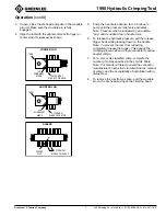
Align the tool with the alignment mark (for lugs) or
center stop (for sleeves) as shown.
5.
Pump the handle to advance ram. Continue to
pump until the pressure relief valve activates.
Note: Pressure relief is indicated by an audible
“pop” and a sudden drop in handle force.
6.
To release the hydraulic pressure, pull the release
trigger back while pressing down on the handle.
Note: To prevent the ram from retracting
completely, release the trigger. This speeds the
crimping process when a single connector requires
several crimps.
7.
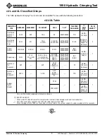
For a cUL or UL classified crimp, complete the
number of crimps specified in the cUL/UL Table.
Note: For brands not listed, consult the connector
manufacturer’s instructions to determine the number
of crimps and the acceptability of installation with a
dieless tool.
8.
To remove the tool from a splice, pull the movable
pin on the die head and open the crimping head.
OUTERMOST
BLADE OF DIE HEAD
LUG
ALIGNMENT
MARK
LONGER LUG
TANG
OUTERMOST
BLADE OF RAM DIE
LUG
ALIGNMENT
MARK
SHORTER LUG
TANG
OUTERMOST
BLADE OF DIE HEAD
CENTER
STOP
SLEEVE


