

8
DRIFTLESS
SPRAYER
Wing Attachment
1.
Place the left and right wings to the sides of the Center Frame. The wheels of the wings will locate to
the outer rear of the sprayer and face toward the power unit.
2.
Release the breakaway mechanism of the Center Frame. You may find it beneficial to strike the end
of the Breakaway Arm with a rubber mallet.
3.
Loosen the Guide ring that is on the Breakaway Arm.
4.
Remove the 1/4" bolts holding the Wing Pivot U-Clamp to the wing.
5.
Remove the Wing Pivot U-Clamps from the wing.
6.
Place the Wing Pivot U-Clamps onto the Breakaway Arm.
7.
Reattach the Wing to the U-Clamps.
8.
Ensure that the U-Clamp is pressed up against the inside of the Breakaway Arm.
9.
Tighten the 1/4" bolts holding the Wing Pivot U-Clamp to the Breakaway Arm.
10. Lock the Guide Ring into position tight against the Wing Pivot U-Clamp closest to the power unit.
Lock with the Guide Ring set screw.
11. Locate the two ropes and handles. Run the longest rope through the left wing rope cleat and the
shorter rope through the right rope cleat and then both ropes through the half moon ring located on
the Three Valve Mount.
12. Run the longest rope to the right upright tube that has two pulley’s on it and place the rope through
one of the pulleys, then run the rope directly across to the left upright tube, through the pulley and
down to the left wing rope pull tab. Run the shortest rope to the right upright tube, through the pulley
and down to the right wing rope pull tab.
13. Tie a tight knot in the very end of the rope. Pull rope back out of the Rope Tab until the knot is tight
against the Rope Tab.
Plumbing Hookup
1.
Locate the Three Valve Mount that holds the On/Off control valves for each spray section and the
pressure regulating valve. Attach the cross plate supplied in the parts bag to the Three Valve Mount
with ¼” square u-bolts. Attach Mount to upright on the Center frame with 1 1/2" square U-bolts.
2.
Adjust height of controls to suit your power unit and user preference. Use the supplied tie straps to
secure the hoses in the appropriate place.
3.
Attach the Universal Mount Bracket and Nozzle Flow Indicator for the Center Boom Section using the
¼” x 2" lg bolts supplied to the support on the solution tank.
4.
Locate the three 1/2" hoses from the Center Boom Section. Cut to desired length and hook the end of
each hose to the hose barbs on the nozzle flow indicator. To avoid confusion, ensure that the position
that each hose exits the shroud of the spray boom corresponds with the position it is installed on the
nozzle flow indicator. Plastic, crimp type hose clamps are located in the parts box.
5.
Attach wing supply hoses to the appropriate wings placing the supply hose underneath the
breakaway arm. Attach the center nozzle flow indicator supply hose and also the bypass hose to the
top of the solution tank. Use the plastic crimp type hose clamps to secure to hose barbs.
ASSEMBLY
Содержание 73-70675
Страница 13: ...11 DRIFTLESS SPRAYER PARTS SECTION PARTS SECTION...
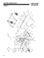
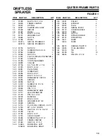
Страница 14: ...12 DRIFTLESS SPRAYER CASTER FRAME PARTS FIGURE 1...
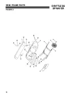
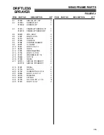
Страница 16: ...14 DRIFTLESS SPRAYER WING FRAME PARTS FIGURE 2...
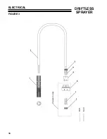
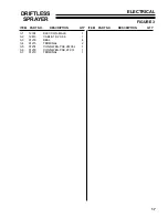
Страница 18: ...16 DRIFTLESS SPRAYER ELECTRICAL FIGURE 3...
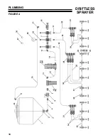
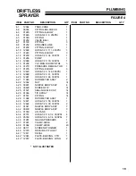
Страница 20: ...18 DRIFTLESS SPRAYER PLUMBING FIGURE 4...
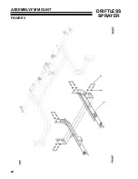
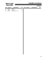
Страница 22: ...20 DRIFTLESS SPRAYER ASSEMBLY FM MOUNT FIGURE 5...
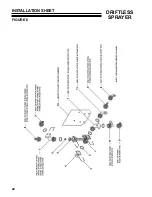
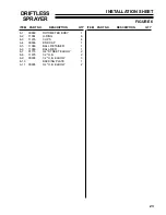
Страница 24: ...22 DRIFTLESS SPRAYER INSTALLATION SHEET FIGURE 6...
Страница 26: ...24 DRIFTLESS SPRAYER CASTER WHEEL ASSEMBLY FIGURE 7...
Страница 28: ...26 DRIFTLESS SPRAYER NOZZLE BODIES FIGURE 8...