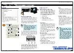


Tiger 320 Series Programming Code Sheet
Draft Copy. Code Version V3.08a
Texmate Inc. Tel. (760) 598 9899 • www.texmate.com
5
2 February, 2005 Prog. Code Sheet V3.08a (NZ101)
0 Functions Activated
by Pressing the
PROGRAM Button
1 Calibration
Procedures
2 Related Calibration
Functions
3 -
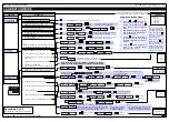
CALIBRATION MODES FOR INPUT AND OUTPUT
0 No function
1 On Demand TARE from the PROGRAM button
2 On Demand Single-point Calibration from the PRO-
GRAM button (requires single input source)
3 On Demand Two-point Calibration from the PROGRAM
button (requires dual input source)
4 On Demand Primary Input Compensation Mode from
the PROGRAM button
5 On Demand Manual Loader Mode (no increase /
decrease with HOLD active)
6 -
7 -
Note:
When in the TARE mode, a decimal point appears at the right
of the display indicating that the tare value is NOT zero.
OBJECT FOR 2nd DIGIT
0
Result
1
Channel 1
2
Channel 2
3
Channel 3
4
Channel 4
CALIBRATION MODE
FIRST DIGIT
SECOND DIGIT
THIRD DIGIT
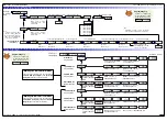
0 Serial Communications Properties
1 Set Auto Zero Maintenance for 3rd digit
2 Set Averaging Samples & Averaging Window for 3rd digit
3 Totalizer Settings Mode
4 Setup 32-point Linearization Tables
5 Scale Analog Output LOW/HIGH Display Readings
6 -
7 -
Use but-
tons to set SPAN
Use
buttons to set
OFFSET
Use but-
tons to set ZERO
Use buttons
to set SCALE
Use buttons
to set SPAN
P
P
For detailed calibration procedures, see
Calibration Procedures Supplement (NZ203)
Press the PROGRAM button for 4 seconds to tare the selected channel
P
P
4 secs
P
4 secs
Use
buttons to set
ZERO
Use buttons
to set SPAN
P
4 secs
P
4 secs
P
P
Use buttons
to set baud rate
Use but-
tons to set parity
Use
buttons to set
address from 1 to 255
Use
buttons to set LOW
display reading [CAL_L]
Use
buttons to set
HIGH display reading [CAL_h]
Use buttons
to set CAL_h
Use buttons
to set time period
Use buttons
to
set total from 1-65535
Select the method of configuring the user defined linearization
table:
manual
or
auto
setup mode. Then set the table number,
date, and serial number before setting the linearization points.
Or select [init] to re-initialize the default table settings.
P
P
P
P
P
P
Use buttons
to
set averag-
ing samples from 0 to 255 counts
Use
buttons to set averaging
window from 0 to 65535 counts
P
Use buttons
to set AZ_M from 0
to 255 counts
P
Auto zero capture band
For detailed calibration procedures, see
Calibration Procedures Supplement
Use
buttons to ADJUST primary input compensa-
tion value from –19999 to 99999 on CH2 ONLY
Use
buttons to set
time delay in milliseconds
Except ASCII Mode which uses message terminators:
Use buttons
to set AZ_A from 0 to
65535 counts
P
Auto zero motion
Auto zero aperture window
0
-
1
Analog Output 1
2
Analog Output 2
THIRD DIGIT
0
-
1
Analog Output 1
2
Analog Output 2
THIRD DIGIT
Note:
The input channel setting in
the 3rd digit is
not
relevant to
the
manual setup mode
.
0
-
1
Total 1
2
Total 2
THIRD DIGIT
Use
buttons to ADJUST analog output 1 or 2 value
from –19999 to 99999 via the manual loader output
Default setting 10,000 counts
0
-
1
CH1
2
CH2
3
CH3
4
CH4
THIRD DIGIT
P
P
Use buttons
to set Cutoff from
–19999 to 32767
P
Use buttons
to
set rollover to ON or OFF
P
Use buttons
to set to 7 or 8 bits
If Code 3 set to Master
Mode [XX2] ONLY
$
= minimum 50 ms delay
*
= minimum 2 ms delay
Use buttons
to set input rate
Note:
The correct input signal channel must be
selected in the 3rd digit when configuring a lin-
earization table using the
auto setup mode
.
Use
buttons to set
AZ_C from 1 to 254 counts
Rate-of-change in counts/second
This is the default 3rd digit box. If not pointing to another 3rd digit
box, all 2nd digit settings should be regarded as pointing to here.
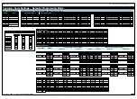
0 Manual Calibration
(requires NO input source)
1 2-point Calibration (requires dual input source)
2 Calibrate Thermocouple (requires K type thermocouple
input source)
3 Calibrate RTD (requires RTD 385 input source)
4 Calibrate Smart Input Module.
Note: This function is not available on all input modules
5 Calibrate Analog Output mA/V (Single analog out requires
multimeter connected to pins 2 and 3 on Terminal 4)
6 -
7 -
Converting °F to °C
See User Notes on Page 20 for a procedure.
2
1
3
+
+
Dual
Analog
Output
(ADV)
Analog Output
TERMINAL 4
All smart input modules have individual calibration procedures.
See the specific smart input module data sheet for setup procedures
Use buttons
to set CAL_L
Using the Calibration Mode
1)
Press the
and
buttons at the
same time. The controller enters the
brightness menu [BRI]. Press the
button again to enter the Calibration
Mode.
2)
With [CAL] [XXX] toggling on the dis-
play, set the 1st, 2nd, and 3rd digits to
their required settings.
3)
Press the
button to enter the select-
ed sub-menu and select the required
calibration settings from the sub-menus
displayed.
4)
Press the
button repeatedly to
return to the operational display
(bypassing Codes 1 to 9).
P
P
P
P
Note:
Once the 3-digit settings
have been entered for an
on-demand function [CAL]
[0XX], pressing the
button saves the selected
on-demand setting and
moves to Code 1.
When in the operational
display, press the
but-
ton for 4 seconds to acti-
vate the selected on-
demand function and dis-
play the relevant sub-menu
settings (except [01X]
which has no sub-menu).
P
P


