Test Equipment
8
Test Equipment
AC Input Source:
The input source is an isolated variable AC source capable of supplying between 85
V
RMS
and 265 V
RMS
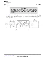
at no less than 5 W and connected as shown in
. For accurate efficiency
calculations, a power meter (PM1) should be inserted between the AC source and the EVM. For highest
accuracy, connect the voltage terminals of the power meter directly across the power source. (Connecting
the voltage terminals directly to the EVM results in a small current error. This is very significant when
measuring no-load power)
Load:
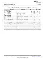
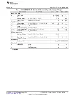
The UCC28880EVM-616 is capable of delivering 100 mA of output current. 50
Ω
, at 1 W is the
minimum value of load resistance for the 5-V output and 130
Ω
at 5 W is the minimum value of load
resistance for the 13-V output. Alternatively an electronic load may be used.
NOTE:
The output is not isolated from the AC and the electronic load must be capable of operating
from a high-voltage input.
Power Meter:
The power analyzer (PM1) is capable of measuring low-input current, typically less than
100 µA, and a long averaging mode if low-power standby mode input power measurements are to be
taken. An example of such an analyzer is the Yokogawa WT210 Digital Power Meter.
Multimeters:
Two digital multimeters are used to measure the regulated output voltage (DMM) and load
current (DMM ).
Oscilloscope:
A digital or analog oscilloscope with a 500-MHz scope probe is recommended.
Recommended Wire Gauge:
A minimum of AWG 24 wire is recommended. The wire connections
between the AC source and the EVM, and the wire connections between the EVM and the load should be
less than two feet long.
10
UCC28880EVM-616 High-Side Buck Evaluation Module
SLUUB56A – July 2014 – Revised August 2014
Copyright © 2014, Texas Instruments Incorporated


