TPS65313 GUI
7
SLDU028A – January 2018 – Revised March 2020
Copyright © 2018–2020, Texas Instruments Incorporated
TPS65313-EVM User’s Guide
6.1
Device Controls Page
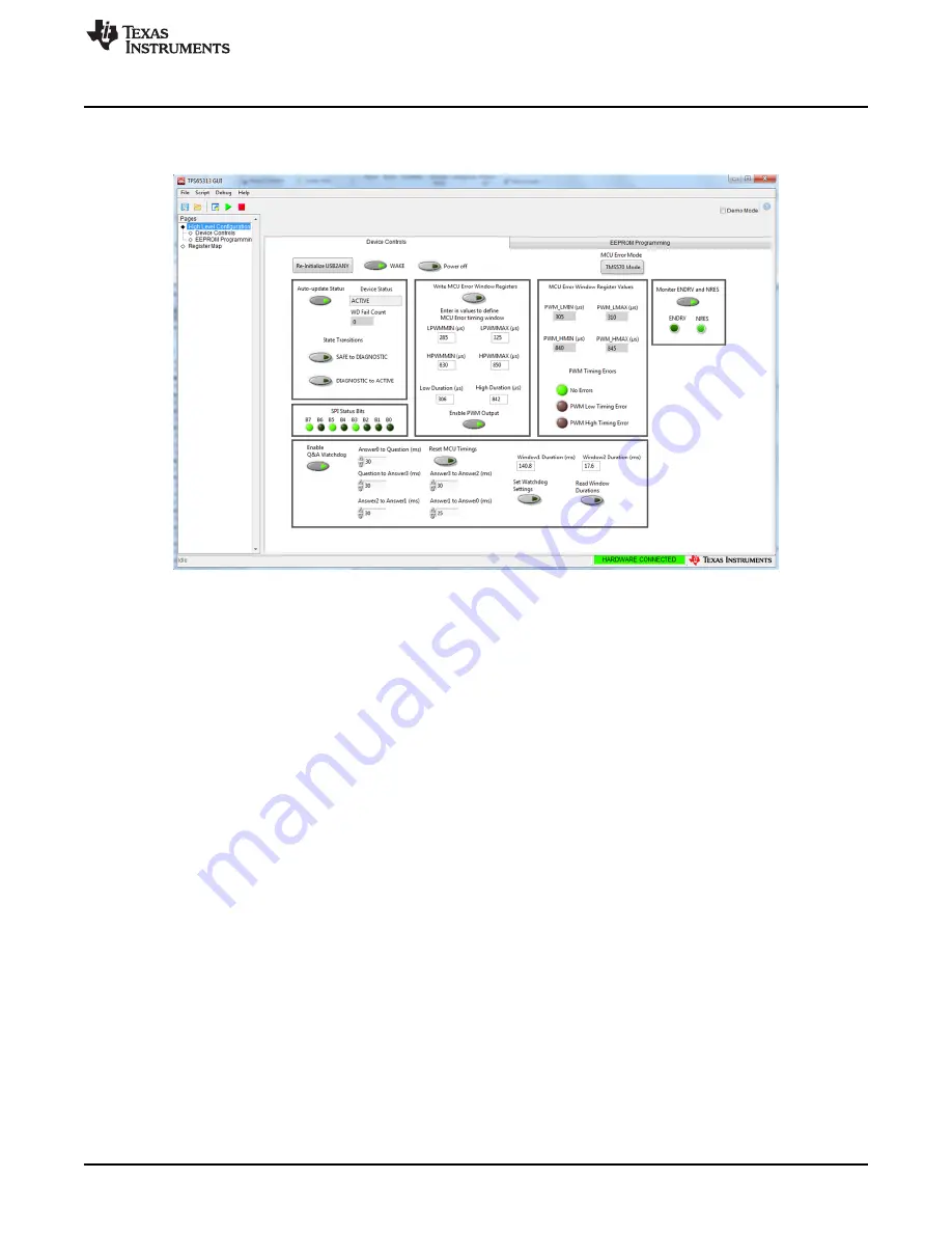
This section describes the different options on the Device Controls page.
Figure 4. TPS65313 GUI Device Controls Page
6.1.1
Re-Initialize USB2ANY Button
After connecting the USB cable to the EVM and launching the GUI, click the
Re-Initialize USB2ANY
button
to sync the GUI with the EVM. If the GUI is successfully synchronized with the EVM, the GUI connection
status field on the bottom right of the GUI turns green and
HARDWARE CONNECTED
is displayed (see
). The GUI is now connected to the EVM. If the GUI is not synchronized correctly,
DEMO MODE
is displayed with a grey background.
6.1.2
WAKE Button
If the J20 jumper is set between pins 2 and 3, clicking the
WAKE
button turns on the high-side transistor
on the VBAT input supply line and this supply voltage is applied on the WAKE pin which starts device
start-up. When the device is successfully powered on, disabling the
WAKE
button has no impact and the
device continues to operate normally. If the
WAKE
button is still enabled and the device enters the OFF
state because of some errors, the device automatically starts to wake up again. If the
WAKE
button is
disabled and the device enters the OFF state because of some errors, the device stays in the OFF state,
and the WAKE button must be clicked again to start the new power-up cycle.
6.1.3
Power Off Button
The
Power off
button makes the WAKE signal low and clears the wake latch using a SPI register write
(CLR_WAKE_LATCH bit) to put the device in the OFF state. The WAKE signal must be applied again to
start the new power-up cycle.
6.1.4
Device Status Update
When the
Auto-update Status
button is enabled, the current state of the device (SAFE, DIAGNOSTIC, or
ACTIVE) is updated automatically. The
WD Fail Count
field shows the current value of the device
watchdog (WD) fail counter.


