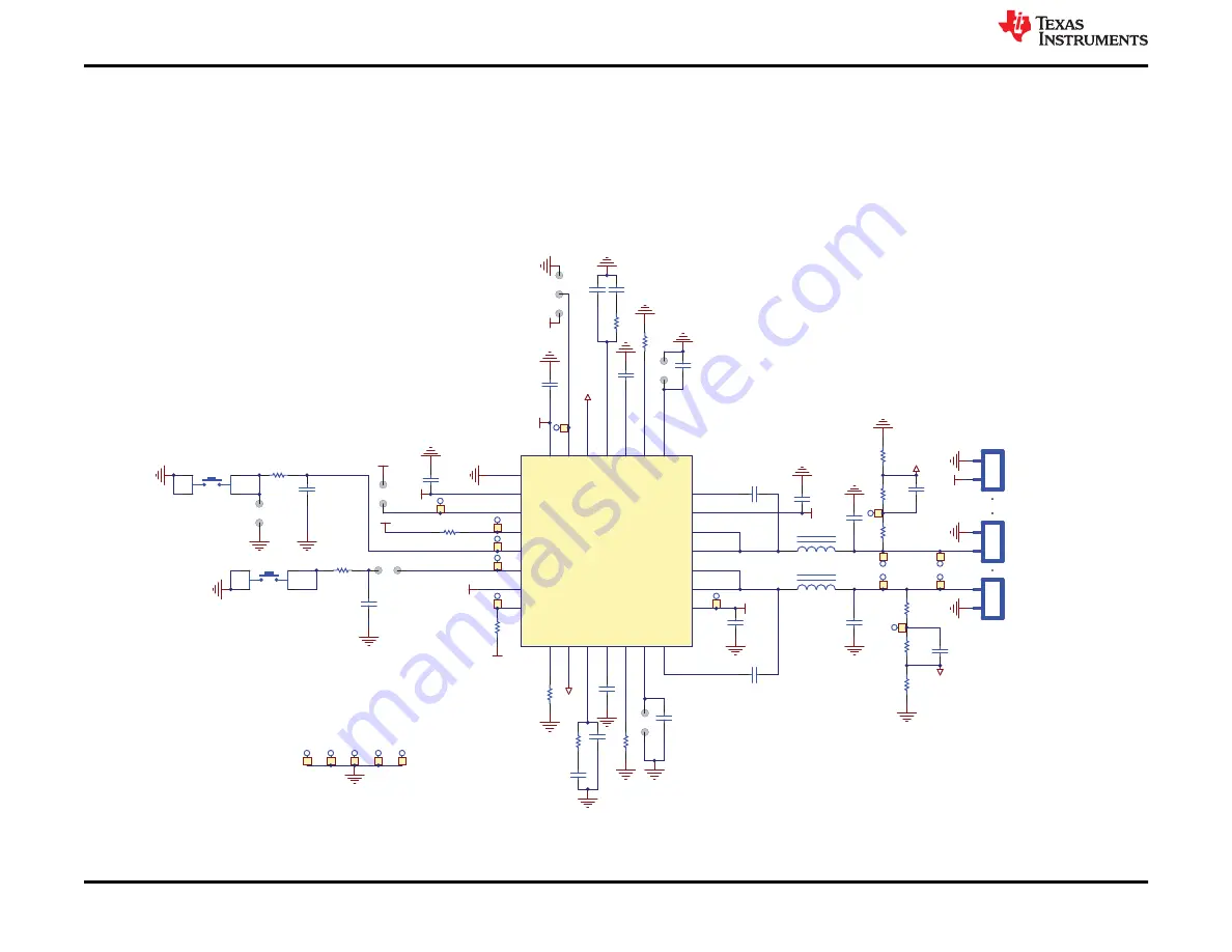
3 Schematic
illustrates the TPS65253 EVM schematic.
prod/folders/print/TPS65253.html
.
Note that for the purpose of gains-phase measurements R9 and R11 (0 Ω on the EVM) need to be replaced by suitable low value resistors as per the
network analyzer setup required. Test points are provided on either end of the resistors to allow for easy measurement. Also, R3, R4, C10, and C12 can
be populated if users desire to reduce overshoot at LX pins due to parasitic L and C resonance.
R
O
S
C
1
F
B
1
2
C
O
M
P
1
3
S
S
1
4
R
L
IM
1
5
E
N
1
6
B
S
T
1
7
VIN1
8
LX1
9
LX1
10
LX2
11
LX2
12
VIN2
13
BST2
14
E
N
2
1
5
R
L
IM
2
1
6
S
S
2
1
7
C
O
M
P
2
1
8
F
B
2
1
9
L
O
W
_
P
/S
D
A
2
0
V
7
V
2
1
V3p3
22
V3p3
23
PGOOD
24
PB
25
MR/SCL
26
LH
27
INT
28
PP
29
U1
TPS65253
3.3uF
C22
TP24
V3p3
100K
R24
0
R25
TP25
TP26
TP28
383K
R1
V7V
V3p3
100K
R28
FB1
1
0
0
p
F
D
N
I
C
3
a
20K
R3
4.7nF
C3
4
.7
n
F
C
4
1
0
0
K
R
5
JP6
4
.7
n
F
C
6
47nF
C7
TP8
10uF
C8
25V
VIN
22uF
C9
40.2K
R9a
80.6K
R9b
4.7nF
C9a
FB1
1
2
J9
4.7uH
L9
4.7uH
L11
1
2
J11
22uF
C11
40.2K
R11a
32K
R11b
4.7nF
C11a
FB2
47nF
C14
10uF
25V
C13
VIN
1
2
J8
VIN
JP15
4.7nF
C15
T
P
2
0
1
5
0
K
R
1
6
4
.7
n
F
C
1
7
1
0
0
p
F
D
N
I
C
1
8
a
2
0
K
R
1
8
4
.7
n
F
C
1
8
FB2
10uF
C21
S
D
A
0
R9
TP9
TP9a
TP9b
0
R11
TP11
TP11b
TP11a
1.8V@2A
1.2V@3A
TP1
TP2
TP3
TP4
TP5
JP20
V3p3
TP23
4.5V
V3p3
V3p3
1
2
3
4
S25
JP25
0.1uF
DNI
C25
1
2
3
4
S26
0.1uF
DNI
C26
JP23
V7V
0
R26
JP26
VOUT2
VOUT1
VIN
Figure 3-1. TPS65253 Schematic
Schematic
4
TPS65253 Buck Converter Evaluation Module User's Guide
SLVU469B – JUNE 2011 – REVISED MAY 2021
Copyright © 2021 Texas Instruments Incorporated


