+
+
+
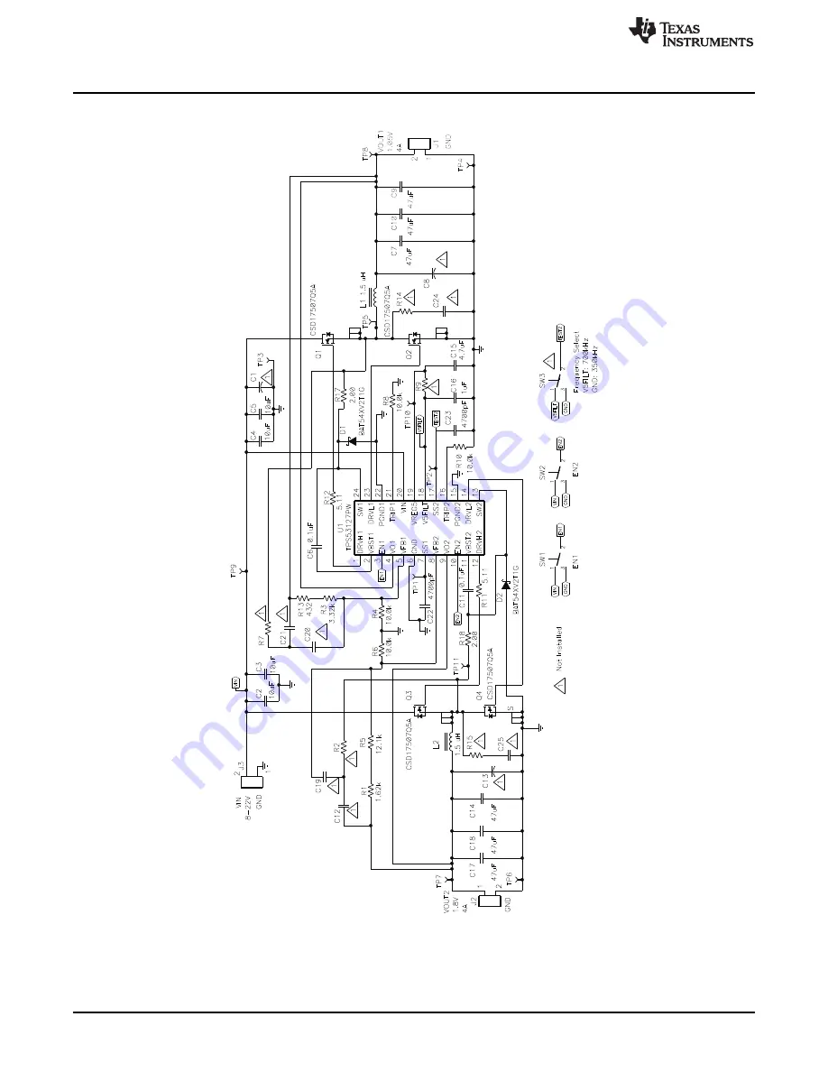
TPS53127EVM-614 Schematic
www.ti.com
3
TPS53127EVM-614 Schematic
NOTE: For Reference Only, See
Table 3
for Specific Values.
Figure 1. TPS53127EVM-614 Schematic
4
TPS53127EVM-614
SLVU434 – February 2011
Submit Documentation Feedback
© 2011, Texas Instruments Incorporated


