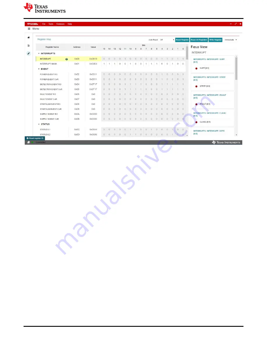
Figure 4-5. Register Map
www.ti.com
TPS23882B1 GUI Setup
SLVUC36 – APRIL 2021
Submit Document Feedback
TPS23882B1EVM: PoE, PSE, TPS23882B1
Evaluation Module
13
Copyright © 2021 Texas Instruments Incorporated
Страница 1: ...with I2C Monitoring 5 2 6 Advanced Test Setup Using MSP EX430FR5969 LaunchPad 6 3 General Use Features 7 3 1 EVM Input Output Connectors and Switches 7 3 2 EVM LEDs 7 3 3 EVM Test Points 8 3 4 EVM Tes...
Страница 2: ...1000BASE T gigabit Ethernet data pass through Single DC power supply input Onboard 3 3 V regulator Onboard I2C interface to the TPS23882B1 device from either USB2ANY or MSP EXP430FR5969 Port ON statu...
Страница 3: ...ides galvanic isolation between the PoE power side and host side using digital isolators ISO7241CD The host side power is provided either from J2 of the mother board from USB2ANY or J5 of the motherbo...
Страница 4: ...wer level and power on the board without the USB2ANY or MSP EXP430FR5969 connected Figure 2 1 illustrates the basic setup using autonomous mode TPS2373 4EVM 758 Class 3 4 Power Supply J7 J1 32 J33 TPS...
Страница 5: ...SB2ANY TPS2373 4EVM 758 Class 3 4 Positive Power Supply J7 J1 32 J33 TPS23882EVM 008 J8 J20 J19 D1 J2 USB2ANY BOOST PSEMTHR 097 Ribbon Cable xxx xxx xx xx xx xxx xxx xxx xx xx xxx xxx PC USB CABLE Eth...
Страница 6: ...EXP430FR5969 J21 J9 Ethernet Cable Positive Negative Figure 2 3 Advanced Setup Using LaunchPad CAUTION If wanting to run TPS23882B1 in semi auto mode remove the jumper installed on J5 of the TPS23882B...
Страница 7: ...r port 5 data only J32 2 Pair Port 5 Two pair port 5 power and data J30 J30 Two pair port 6 data only J33 2 Pair Port 6 Two pair port 6 power and data J24 J24 Two pair port 7 data only J21 2 Pair Port...
Страница 8: ...GND VPWR ground TP4 WHT SDA I2C Data from LaunchPad and USB TO GPIO TP5 WHT SCL I2C Clock from LaunchPad and USB TO GPIO TP6 WHT PSE_SDAO I2C data out from TPS23882B1 TP7 WHT PSE_SCL I2C clock to TPS2...
Страница 9: ...1 2 P4 Two pair port 4 LED bias J26 1 2 P5 Two pair port 5 LED bias J25 1 2 P6 Two pair port 6 LED bias J14 1 2 P7 Two pair port 7 LED bias J13 1 2 P8 Two pair port 8 LED bias Daughterboard TPS23882B1...
Страница 10: ...e default device address in the GUI is set to 0x20 which matches the default configuration of the EVM J4 on the daughter card is installed with jumpers The GUI sets the TPS23882B1 in configuration B m...
Страница 11: ...neering View On the page displayed in Figure 4 4 each port can be configured separately by clicking each RJ45 connector By default the TPS23882B1 is configured in OFF Mode Each port can be configured...
Страница 12: ...45 connector If the port is configured in Auto Mode the port will turn on automatically by the PSE device after connecting a valid PD If not configured in Auto Mode a port enable command is required T...
Страница 13: ...Figure 4 5 Register Map www ti com TPS23882B1 GUI Setup SLVUC36 APRIL 2021 Submit Document Feedback TPS23882B1EVM PoE PSE TPS23882B1 Evaluation Module 13 Copyright 2021 Texas Instruments Incorporated...
Страница 14: ...e Composer Studio 7 2 0 2 OK the workspace location and CCS starts 3 Import the project Project Import CCS Projects make sure you are in CCS Edit mode 4 Navigate to the project location then click the...
Страница 15: ...Semi Auto UART Transmission Status www ti com TPS23882B1 GUI Setup SLVUC36 APRIL 2021 Submit Document Feedback TPS23882B1EVM PoE PSE TPS23882B1 Evaluation Module 15 Copyright 2021 Texas Instruments In...
Страница 16: ...ted in the MSP430 reference code and Figure 4 8 shows the flow chart Basically after configuration the TPS23882B1 handles port detection classification turn on and faults by itself and there is no con...
Страница 17: ...ction Event Get Disconnect Status Determine port s Classification Event Get Classification Status Determine port s Power On Port PPM Classification Valid Print Status Fault Event Get Fault Status Dete...
Страница 18: ...oard schematics Figure 5 1 BOOST PSEMTHR8 097 Motherboard Schematic Control EVM Schematic Layout Guidelines PCB Assembly and Layer Plots www ti com 18 TPS23882B1EVM PoE PSE TPS23882B1 Evaluation Modul...
Страница 19: ...d Schematic Power Ports www ti com EVM Schematic Layout Guidelines PCB Assembly and Layer Plots SLVUC36 APRIL 2021 Submit Document Feedback TPS23882B1EVM PoE PSE TPS23882B1 Evaluation Module 19 Copyri...
Страница 20: ...3 5 6 Q6 PSE_D1 PSE_D2 PSE_D3 PSE_D4 PSE_D5 PSE_D6 PSE_D7 PSE_D8 CH1_SEN CH2_SEN CH3_SEN CH4_SEN CH5_SEN CH6_SEN CH7_SEN CH8_SEN CH1_GATE CH2_GATE CH3_GATE CH4_GATE CH5_GATE CH6_GATE CH7_GATE CH8_GATE...
Страница 21: ...imize the impact of PCB trace resistance Refer to Figure 5 10 as an example 5 2 3 Ground Plane Spacing and Isolation GND GND1 and EARTH nets Appropriate spacing should be provided between the GND GND1...
Страница 22: ...5 6 BOOST PSEMTHR8 097 Motherboard Layer 2 Routing EVM Schematic Layout Guidelines PCB Assembly and Layer Plots www ti com 22 TPS23882B1EVM PoE PSE TPS23882B1 Evaluation Module SLVUC36 APRIL 2021 Subm...
Страница 23: ...BOOST PSEMTHR8 097 Motherboard Bottom Side Routing www ti com EVM Schematic Layout Guidelines PCB Assembly and Layer Plots SLVUC36 APRIL 2021 Submit Document Feedback TPS23882B1EVM PoE PSE TPS23882B1...
Страница 24: ...ard Top Side Routing Figure 5 11 TPS23882B1EVM 008 Daughterboard Bottom Side Routing EVM Schematic Layout Guidelines PCB Assembly and Layer Plots www ti com 24 TPS23882B1EVM PoE PSE TPS23882B1 Evaluat...
Страница 25: ...ard Bottom Side Assembly www ti com EVM Schematic Layout Guidelines PCB Assembly and Layer Plots SLVUC36 APRIL 2021 Submit Document Feedback TPS23882B1EVM PoE PSE TPS23882B1 Evaluation Module 25 Copyr...
Страница 26: ...CAP CERM 1000 pF 50 V 10 X7R 0402 0402 885012205061 Wurth Elektronik D1 1 White LED True Green SMD 2 8x3 2mm LT E6SG AABB 35 1 OSRAM D2 1 58V Diode TVS Uni 58 V 93 6 Vc SMC SMC SMCJ58A 13 F Diodes In...
Страница 27: ...W AEC Q200 Grade 0 0603 0603 CRCW060347K0JNEA Vishay Dale R6 1 6 04k RES 6 04 k 1 0 1 W AEC Q200 Grade 0 0603 0603 CRCW06036K04FKEA Vishay Dale R10 R13 2 4 7k RES 4 7 k 5 0 1 W AEC Q200 Grade 0 0603 0...
Страница 28: ...B SOIC 16 DW0016B ISO7241CDW Texas Instruments U3 1 Single Buffer Driver With Open Drain Output DCK0005A LARGE T R DCK0005A SN74LVC1G07DCKR Texas Instruments C2 C5 C20 0 1 F CAP CERM 1 F 10 V 10 X7R 0...
Страница 29: ...y 8 100V MOSFET N CH 100 V 5 A DNH0008A VSONP 8 DNH0008A CSD19538Q3A Texas Instruments None 8 0 2 RES 0 2 1 0 333 W 0805 0805 RL1220S R20 F Susumu Co Ltd 1 124k RES 124 k 1 0 125 W AEC Q200 Grade 0 08...
Страница 30: ...J 6ENF2262V Panasonic 0 15 8k RES 15 8 k 1 0 125 W AEC Q200 Grade 0 0805 0805 ERJ 6ENF1582V Panasonic 0 11 0k RES 11 0 k 1 0 125 W AEC Q200 Grade 0 0805 0805 ERJ 6ENF1102V Panasonic 0 7 68k RES 7 68 k...
Страница 31: ...change without notice TI grants you permission to use these resources only for development of an application that uses the TI products described in the resource Other reproduction and display of thes...