


Board Connectors and Components
6
SNOU157A – March 2018 – Revised April 2018
Copyright © 2018, Texas Instruments Incorporated
TMP1075EVM User's Guide
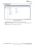
3.8
I2C Slave Addresses – (R15, R16)
TMP1075 is capable of supporting up to 32 I2C 7-bit addresses. The TMP1075 is connected to the bus by
a unique slave address to operate data transfer from the master-transmitter to the slave-receiver or the
slave-transmitter to the master-receiver. The TMP1075 can be configured desired two serial bus
addresses depending on the state of the A0, A1, and A2 as
. The EVM can be configured up to
two addresses. At default, the resistor R16 is soldered, and configured for 0x48h address. For more
details information, refer to the
Address Pins and Slave Addresses for the TMP1075
table in the
Temp Sensor With I2C and SMBus Interface in Industry Standard LM75
data sheet (SBOS854).
Table 3. I2C Slave Addresses
CORRESPONDING EVM
RESISTOR
ADDRESS PIN CONNECTION
SLAVE ADDRESS
A2
A1
A0
BINARY
HEX
R15
GND
GND
GND
1001000
0x48
R16
GND
GND
V+
1001001
0x49
4
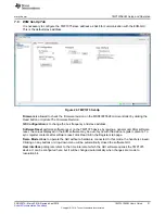
System Setup
The TMP1075EVM hardware consists of the USB2ANY Platform and the TMP1075EVM altogether in one
single board. The unit is easily connected through USB connector into the computer as shown in
.
Figure 3. TMP1075EVM Hardware Setup