OPEN
Power Supplies
6
SBAU247A – June 2015 – Revised September 2019
Copyright © 2015–2019, Texas Instruments Incorporated
TLV2553EVM-PDK Evaluation Module
4
Power Supplies
The PHI provides multiple power-supply options for the EVM, derived from the computer USB supply.
The EEPROM on the TLV2553EVM uses a common 3.3-V power supply and the digital level translator
uses a separate 3.3-V supply (both directly from the PHI). On the other hand, the ADC and analog input
drive circuits are powered by the TPS7A4901 onboard the EVM, which is a low-noise linear regulator that
uses the 5-V supply out of a switching regulator on the PHI to generate a much cleaner 5-V output.
The power supply for each active component on the EVM is bypassed with a ceramic capacitor placed
close to that component. Additionally, the EVM layout uses thick traces or large copper fill areas where
possible between bypass capacitors and their loads to minimize inductance along the load current path.
5
TLV2553EVM-PDK Initial Setup
This section explains the initial hardware and software setup procedure that must be completed for
properly operating the TLV2553EVM-PDK.
5.1
Default Jumper Settings
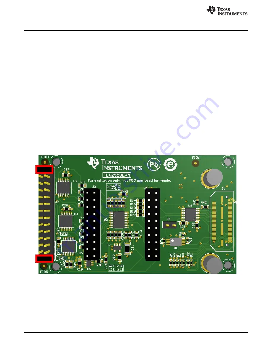
Upon unpacking, the EVM is already configured with default jumper settings. J5 must be open and J2
must have shunts installed at the locations shown in
Figure 3. TLV2553EVM Default Jumper Settings


