Typically, a high-resolution analog-to-digital converter (ADC) then follows the PGA to digitize the amplified voltage. Given that
the signals being measured usually are changing slowly, and that very high resolution is required, delta-sigma topologies are
often used to implement the ADC. As with the gain stage, the stability of the ADC overtime and temperature is very important
so as not to limit overall performance.
2.2.2 Body Composition Measurement Analog Front-End
The AFE4300 provides two options for body impedance measurement: ac rectification and I/Q demodulation. Both options
work by injecting a sinusoidal current into the body and measuring the voltage across the body. The portion of the circuit
injecting the current into the body is the same for each of those options. The difference, however, lies in how the measured
voltage across the impedance is processed to obtain the final result.
2.2.2.1 AC rectification
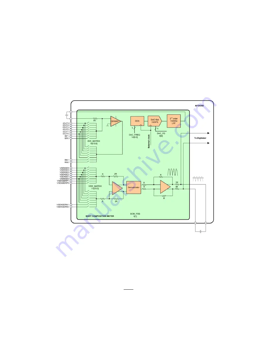
Figure 5 BCM in AC Rectifier Mode
The top portion of Figure 5 represents the current-injection circuit. A direct digital synthesizer (DDS) generates a sinusoidal
digital pattern with a frequency obtained by dividing a 1-MHz clock with a 10-bit counter. The digital pattern drives a 6-bit, 1-
MSPS DAC. The output of the DAC is filtered by a 150-kHz, second-order filter to remove the images, followed by a series
external capacitor to block the dc current and avoid any dc current injection into the body. The output of the filter (after the dc
blocking capacitor) drives a resistor setting the amplitude of the current to be injected in the body:
Current flows into the body through an output analog multiplexer (MUX) that allows the selection of up to six different contact
points on the body. The same MUX allows the connection of four external impedances for calibration. The current crosses the
body impedance and a second MUX selects the return path (contact) on the body, closing the loop to the output of the
amplifier.


