www.ti.com
Using the GUI Software
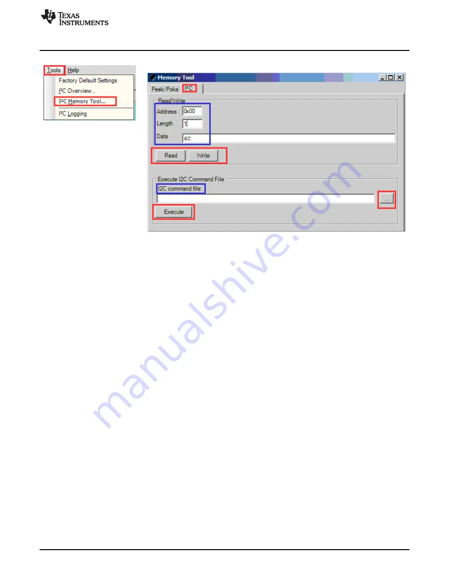
Figure 20. I2C Memory Tool
17
SLOU331A – December 2011 – Revised August 2014
TAS5731EVM Evaluation Module
Submit Documentation Feedback
Copyright © 2011–2014, Texas Instruments Incorporated
Страница 1: ...he DRC Function 14 3 6 Using the Mixer and Scaler Nodes 16 3 7 Using I2C Memory Tool 16 4 Jumpers and Control Utilities on MC57xxPSIA board 18 4 1 RCA OPTICAL Jumpers 18 4 2 Switches 18 4 3 LED Indica...
Страница 2: ...s Instruments The TAS5731 combines a high performance PWM processor with a class D audio power amplifier This EVM can be configured with two single ended speakers with a BTL subwoofers 2 1 or two brid...
Страница 3: ...System and EVM Signal Path Overview 1 1 TAS5731EVM and MC57xxPSIA Features Channel evaluation module design Self contained protection systems and control pins USB interface Standard I2 S data input us...
Страница 4: ...wer Supply PVDD Banana plug test leads for power supplies and speakers Optical or coaxial cable for SPDIF interface based on signal source USB cable EVM software Speakers or Loads for outputs The foll...
Страница 5: ...d maximum supply voltage in the TAS5731 data sheet SLOS726 2 1 3 Loudspeaker Connectors CAUTION All speaker outputs are biased at VCC 2 and must not be connected to ground e g through an oscilloscope...
Страница 6: ...confirming that a viable signal is available to the device Install a jumper on JP4 across the middle pin and the pin marked SPDIF to connect the digital source to SDIN1 Install a jumper on JP5 to conn...
Страница 7: ...AS5731EVM product page The TI Web site always has the latest release and any updates to versions of the GUI Execute the GUI install program Setup exe Once the program is installed the program group an...
Страница 8: ...m The main function of the GUI is to provide the user an easy way to manipulate the device register space for attaining the required signal processing flow The block diagram of the Digital Audio Proce...
Страница 9: ...e System Properties window right click on My Computer Icon and click Properties This brings up the properties window Select the Advanced tab and click on Environment variables as shown in Figure 8 Fig...
Страница 10: ...ruments Inc title in the start program menu NOTE PPSI2C variable should be set before the GUI interface or the memory tool is opened If the GUI was opened prior to setting the environment variable Ste...
Страница 11: ...ties menu seen on the right hand side of the GUI window Figure 10 is used to specify the device to be used A zoomed snap shot of the properties menu is shown in Figure 11 Select TAS5731 from the Curre...
Страница 12: ...ly two additional operations exit shutdown and un mute The device shut down mode can be toggled through the Shutdown Checkbox highlighted with a red box in Figure 13 Uncheck this box to bring the devi...
Страница 13: ...he properties window Double Clicking on the BQ block opens up the Filter creation tool window The Figure 15 shows the filter creation window corresponding to block BQ1 where eight Bi Quad registers ar...
Страница 14: ...he DRC function in the GUI the DRC control should be updated to the Enabled state Note that the DRC 1 and DRC 2 have independent enable disable controls Figure 16 TAS57X1 GUI DRC Blocks The different...
Страница 15: ...nts window that can be opened by clicking on the Time Constants in DRC customization tool The time constant window snap shot is shown in Figure 18 Figure 18 DRC Time Constants Window 15 SLOU331A Decem...
Страница 16: ...shown in Figure 20 or can also be launched stand alone even when the GUI window is not opened through the Windows All Programs Texas Instruments Inc I2C Memory tool option The stand alone capability i...
Страница 17: ...om Using the GUI Software Figure 20 I2C Memory Tool 17 SLOU331A December 2011 Revised August 2014 TAS5731EVM Evaluation Module Submit Documentation Feedback Copyright 2011 2014 Texas Instruments Incor...
Страница 18: ...switch S2 resets the TAS5731 device USB RESET S1 resets the USB bus Pressing PDN S4 powers down the TAS5731 4 3 LED Indicators LED1 USB Power connector installed at J1 LED2 3 3V Power is valid LED3 RC...
Страница 19: ...EVM Board Layouts Figure 21 illustrates the TAS5731EVM top composite assembly Figure 21 TAS5731EVM Top Composite Assembly 5 2 TAS57xx PSIA Board Layout Figure 22 shows the TAS57xxPSIA top composite as...
Страница 20: ...0 1ufd 50V 0603 C22 PGND PGND PGND 330pfd 50V 0603 C28 18 0603 R13 10ufd 16V VS B C1 0 1ufd 10V 0603 C11 PGND L1 DG6045C 15uH 15uH DG6045C L2 L3 DG6045C 15uH 15uH DG6045C L4 JST VH2 RA 2 1 OUTAB OUT 1...
Страница 21: ...M221BJ 2 C16 C23 P10419TB CAP ALUM ELEC M RADIAL 220UFD 35V 20 ROHS DIGI KEY PANASONIC 15 ERJ 3GEY0R00V 1 R3 P0 0GCT RESISTOR SMD0603 0 0 OHM 5 THICK FILM 1 10W ROHS DIGI KEY PANASONIC 16 ERJ 3GEYJ180...
Страница 22: ...anged schematic for revision A 20 Changed contents of the BOM 21 NOTE Page numbers for previous revisions may differ from page numbers in the current version 22 Revision History SLOU331A December 2011...
Страница 23: ...dling and use of EVMs and if applicable compliance in all respects with such laws and regulations 10 User has sole responsibility to ensure the safety of any activities to be conducted by it and its e...
Страница 24: ...his equipment generates uses and can radiate radio frequency energy and if not installed and used in accordance with the instruction manual may cause harmful interference to radio communications Opera...
Страница 25: ...age et ayant un gain admissible maximal et l imp dance requise pour chaque type d antenne Les types d antenne non inclus dans cette liste ou dont le gain est sup rieur au gain maximal indiqu sont stri...
Страница 26: ...sponsible for compliance with all legal regulatory and safety related requirements concerning its products and any use of TI components in its applications notwithstanding any applications related inf...