


swru197e
17/23
8.3
Forced boot recovery mode
If, for some reason, the firmware update fails and the CC Debugger appears to be non responsive,
there is a way to force the board to only run the bootloader and stop all further execution. In this mode,
no attempts will be made to start the firmware, and the board will only allow the user to perform a new
firmware upgrade over USB.
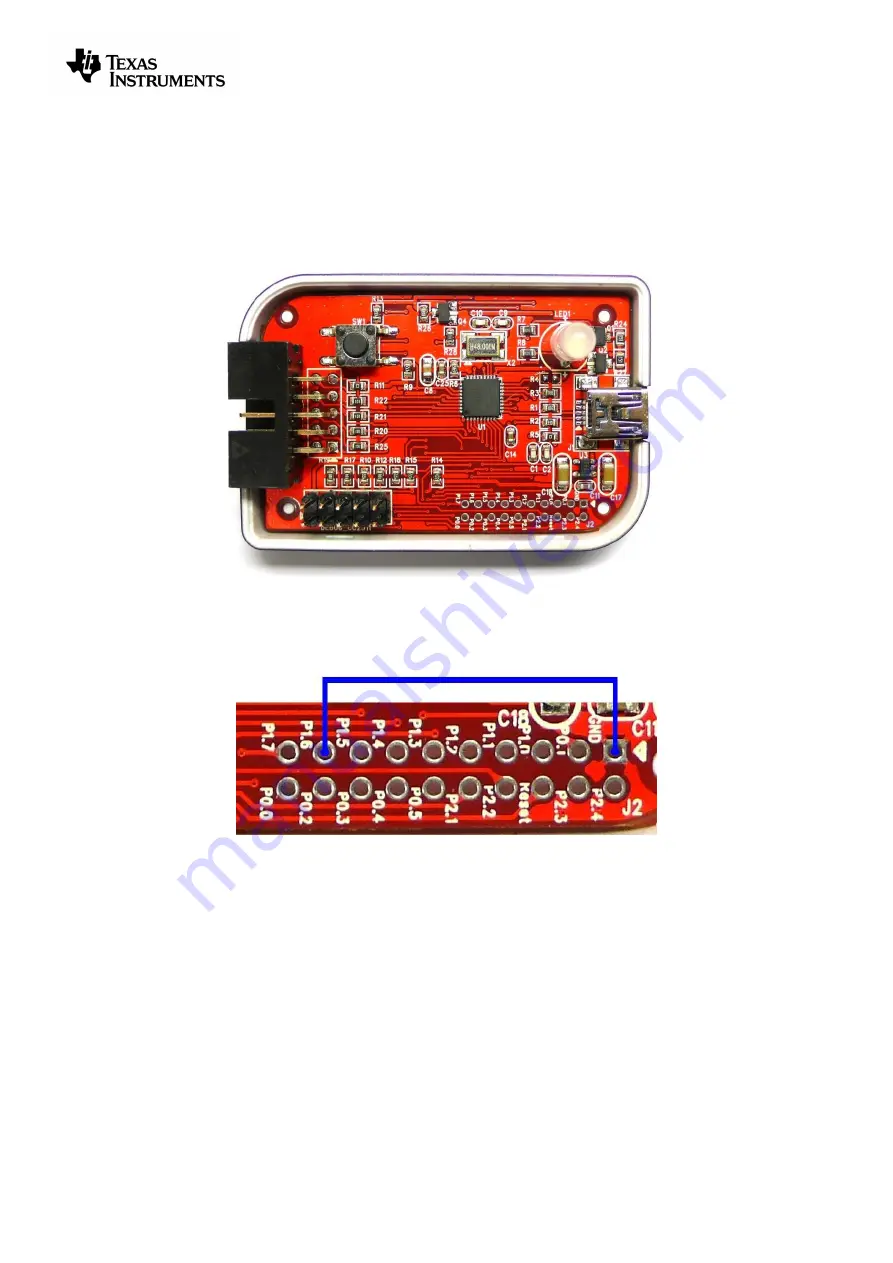
Disconnect the debugger from any power source and open the plastic enclosure.
Figure 14 - Internal view of CC Debugger
Short circuit the pins as depicted in Figure 15: P1.6 on the CC2511 must be connected to GND during
the power-on reset to enter boot recovery mode.
Figure 15 - Short-circuit pins for boot recovery mode
When reconnecting the USB cable, the LED will start to blink with a RED light. This indicates that the
bootloader is running and that the debugger is in boot recovery mode.
At this point, follow the same firmware programming steps as describe at the beginning of this chapter.
Please also note that the boot recovery mode can be used as a check to verify that the bootloader on
the debugger is working.
8.4
Resurrecting the CC Debugger
If the CC Debugger appears to be completely dead when applying power, there is a way to “unbrick”
the board. The method consists of reprogramming the bootloader on the debugger using the debug
connector inside the box. This will require an extra programming device.
When opening the box, locate the debug connector header next to the target connector. Connect this
header to another CC Debugger (see Figure 16) or to a SmartRF05EB (see Figure 17). When using
Содержание SWRU197E
Страница 1: ...CC Debugger User s Guide SWRU197E ...
Страница 23: ......


