Board Layout
www.ti.com
4
SCEU015 – May 2019
Submit Documentation Feedback
Copyright © 2019, Texas Instruments Incorporated
SN74AXC4T774 Evaluation Module User Guide
2
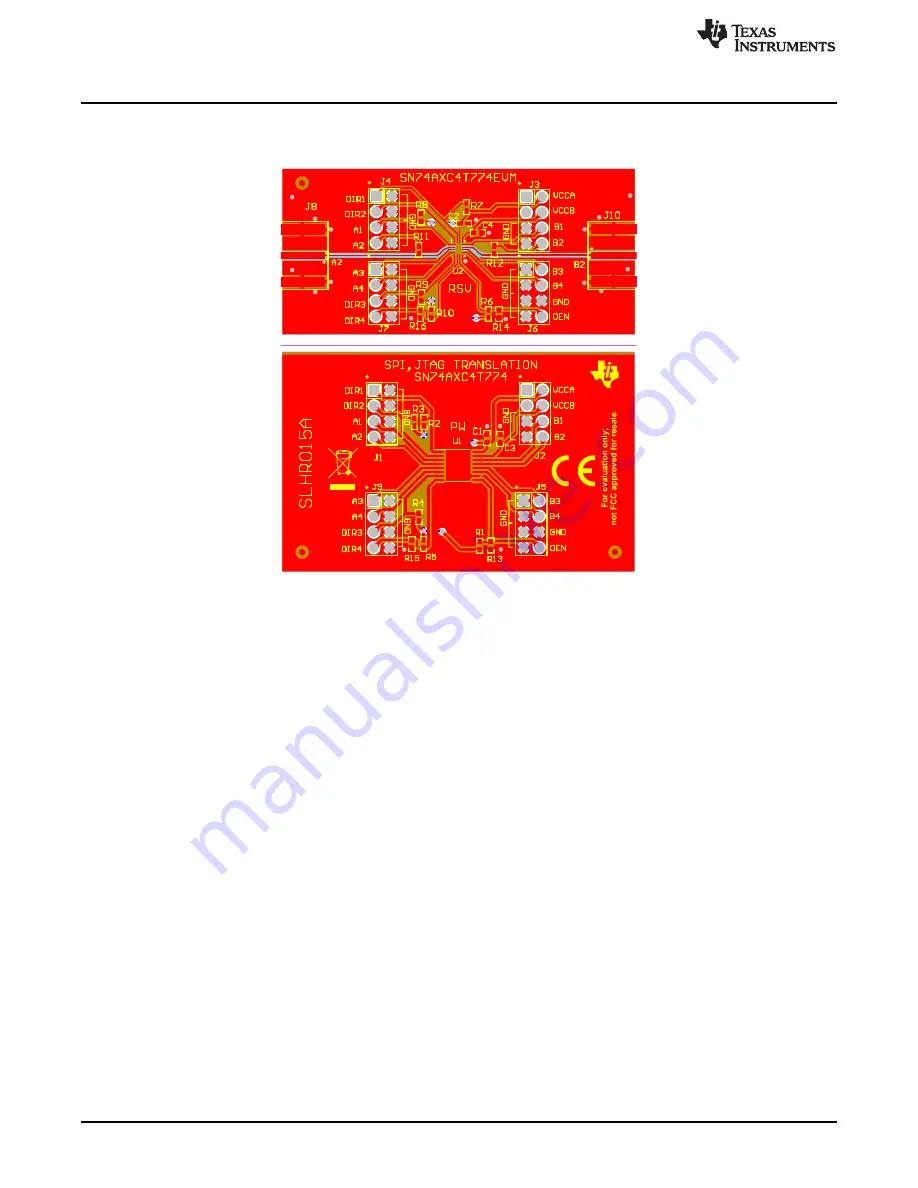
Board Layout
Figure 2
illustrates the SN74AXC4T774EVM layout.
Figure 2. SN74AXC4T774EVM Layout


