www.ti.com
PCB Construction
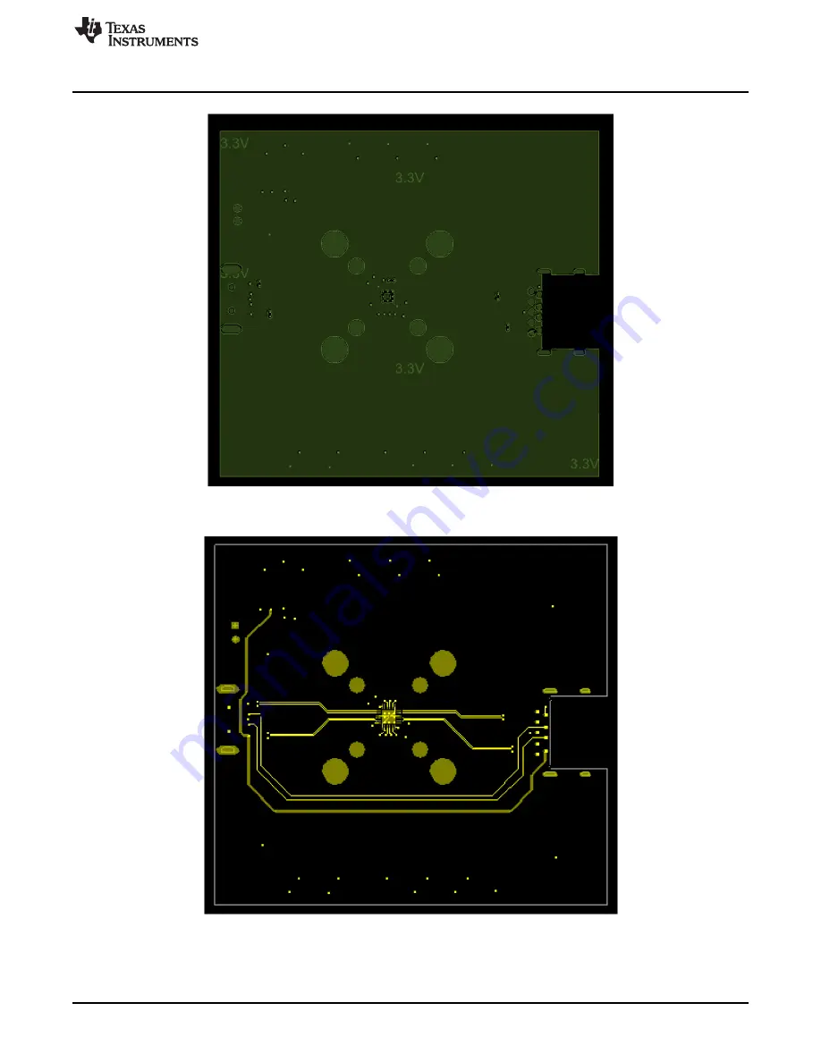
Figure 7. PCB Layout of Third Layer
Figure 8. PCB Layout of Bottom Layer
7
SLLU213 – February 2015
SN65LVPE512 EVM
Submit Documentation Feedback
Copyright © 2015, Texas Instruments Incorporated
Страница 1: ...s Schematics printed circuit board PCB layout images and a bill of materials BOM for this module are included in this user s guide Contents 1 Introduction 2 2 LVPE512 Evaluation Module 2 3 Kit Content...
Страница 2: ...ts 1 SN65LVPE512 Evaluation Module This user manual 3 1 Operational Description of EVM This EVM facilitates the simple evaluation of the LVPE512 USB 3 0 redriver by providing an easy and efficient met...
Страница 3: ...zation channel 1 2 0 dB SW3 OS1 Output swing channel 1 2 1241 mVpp SW4 DE2 De emphasis channel 2 2 0 dB SW5 EQ2 Equalization channel 2 2 0 dB SW6 OS2 Output swing channel 2 2 1241 mVpp SW7 EN_RXD 1 En...
Страница 4: ...tion www ti com Figure 2 Schematic of EQ Control Pins Figure 3 Schematic of Device Control Pins 4 SN65LVPE512 EVM SLLU213 February 2015 Submit Documentation Feedback Copyright 2015 Texas Instruments I...
Страница 5: ...www ti com PCB Construction Figure 4 Schematic of Power Pins 5 SLLU213 February 2015 SN65LVPE512 EVM Submit Documentation Feedback Copyright 2015 Texas Instruments Incorporated...
Страница 6: ...Figure 5 through Figure 8 illustrate the SN65LVPE512 PCB layouts Figure 5 PCB Layout of Top Layer Figure 6 PCB Layout Second Layer 6 SN65LVPE512 EVM SLLU213 February 2015 Submit Documentation Feedback...
Страница 7: ...com PCB Construction Figure 7 PCB Layout of Third Layer Figure 8 PCB Layout of Bottom Layer 7 SLLU213 February 2015 SN65LVPE512 EVM Submit Documentation Feedback Copyright 2015 Texas Instruments Incor...
Страница 8: ...9D C23 4 C17 C24 C27 0 1 F 587 1227 2 ND cc0402 LMK105BJ104KV F C29 2 C18 C25 0 01 F 399 1011 2 ND cc0402 C0402C100J5GACTU 1 C28 10 F 587 3383 2 ND cc0603 JMK107ABJ106MAHT 1 JMP1 Header 2x1 10046483 2...
Страница 9: ...ing the warranty period to the address designated by TI and that are determined by TI not to conform to such warranty If TI elects to repair or replace such EVM TI shall have a reasonable time to repa...
Страница 10: ...essful communication This radio transmitter has been approved by Industry Canada to operate with the antenna types listed in the user guide with the maximum permissible gain and required antenna imped...
Страница 11: ...ified allowable ranges some circuit components may have elevated case temperatures These components include but are not limited to linear regulators switching transistors pass transistors current sens...
Страница 12: ...REMOVAL OR REINSTALLATION ANCILLARY COSTS TO THE PROCUREMENT OF SUBSTITUTE GOODS OR SERVICES RETESTING OUTSIDE COMPUTER TIME LABOR COSTS LOSS OF GOODWILL LOSS OF PROFITS LOSS OF SAVINGS LOSS OF USE L...
Страница 13: ...sponsible for compliance with all legal regulatory and safety related requirements concerning its products and any use of TI components in its applications notwithstanding any applications related inf...