background image

www.ti.com

Setup of Demo System

5

Setup of Demo System

The following sections describe how to setup a demo with and without the Sensor Hub BoosterPack, and
also for custom configuring and operation of the device.

5.1

Set up the RF430FRL152HEVM With Sensor Hub Demo Using the PC

This section describes how to setup and run the Sensor Hub BoosterPack demo. With this setup, the
RF430FRL152HEVM samples over I

2

C three different sensors on the SensorHub BoosterPack. They are

temperature and humidity (SHT21) and a light sensor (ISL29023). After collecting the samples, the data is
transmitted over RF to the TRF7970AEVM which reports them to the PC application. Finally the results
are plotted on the graphs.

1. Connect the TRF7970AEVM to the PC with a USB cable.

2. On the RF430FRL152HEVM, use a pencil or pen to position the switches as shown in

Table 2

Table 2. Switch Positions For Sensor Hub Operation

Switch ID

Position

Comment

S6

Supply

This will source power from the USB cable

S5

0

Does not matter what state this switch is in

S4

0

Does not matter what state this switch is in

S3

M

Device starts in I

2

C/SPI master mode

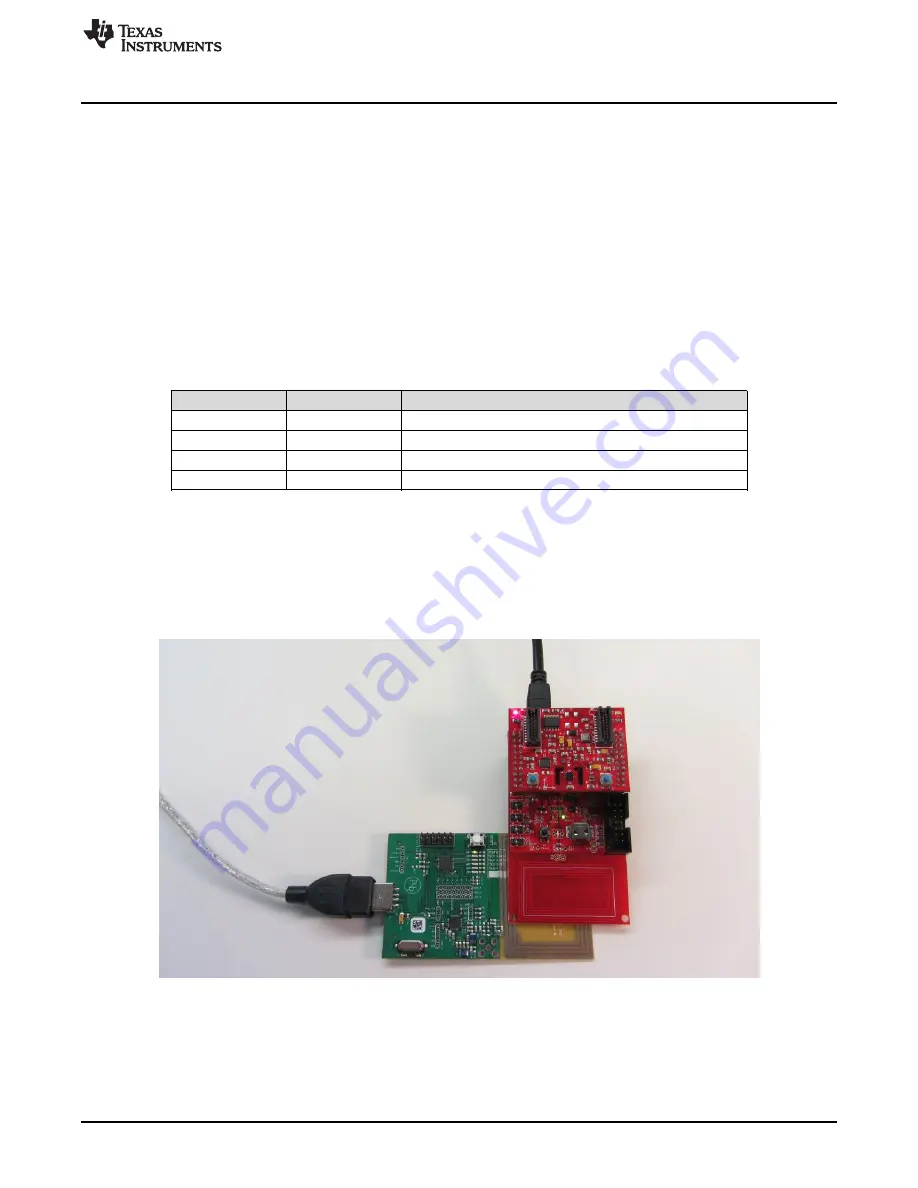
3. Attach the Sensor Hub BoosterPack on top of the RF430FRL152HEVM. Make sure that the orientation

is correct (see

Figure 14

).

4. Connect the RF430FRL152HEVM to the PC using the provided USB cable. Note that this USB

connection is only for the power supply, and no data is passed through it.

5. Position the RF430FRL152HEVM antenna on the antenna portion of the TRF7970AEVM as shown in

Figure 14

. It is recommended to have an insulator between the two antennas or to hold them at a

distance from each other to prevent any short circuits.

Figure 14. BoosterPack Configuration

6. Open the RF430FRL15xH GUI Interface application by going to the Start menu

All Programs

Texas

Instruments

RF430FRL152H GUI .

7. Click the "Connect to TRF7970AEVM" button on the bottom of the window.

8. A few seconds after you click the "Connect" button, the label next to the button should show

"Connected to TRF7970AEVM on COMx". If this is not shown, then a connection has not been made.

19

SLAU607 – December 2014

RF430FRL152HEVM User's Guide

Submit Documentation Feedback

Copyright © 2014, Texas Instruments Incorporated

Содержание RF430FRL152HEVM

Страница 1: ... 30 List of Figures 1 RF430FRL152HEVM 3 2 TRF7970AEVM 3 3 Sensor Hub BoosterPack 4 4 RF430FRL152HEVM Block Diagram 5 5 RF430FRL152HEVM Hardware 6 6 PC Application 8 7 Setup Tab 9 8 Demo Tab 10 9 General Device Configuration Tab 11 10 Sensor Configuration Tab 14 11 Alarm Control Tab 15 12 Sensor Threshold Configuration 17 13 View Sensor Data Tab 18 14 BoosterPack Configuration 19 15 Position the EV...

Страница 2: ...n conjunction with a PC application or a custom NFC RFID capable handset Features and benefits of the RF430FRL152H MCU include ISO IEC 15693 RF interface Low voltage MSP430 MCU L092 based Nonvolatile low power FRAM memory 2kB Sigma delta 14 bit analog to digital converter Single cell battery 1 5 V operation Can run batteryless from RF scavenged energy provided by NFC RFID reader Supports temperatu...

Страница 3: ...ID communication with the RF430FRL152HEVM TRF7970AEVM 1 3 1 TRF7970AEVM Figure 2 shows a photograph of the TRF7970AEVM If the TRF7970AEVM was purchased around the same time as the RF430FRL152HEVM no code updates will be necessary If there are communication issues with the RF430FRL152HEVM make sure that the TRF7970AEVM is programmed with the latest firmware The latest firmware for the TRF7970AEVM c...

Страница 4: ...re available at www ti com tool RF430FRL152HEVM To install the PC GUI 1 Download the RF430FRL152HEVM 1 1 2 windows installer exe file to the PC 2 Run the executable and follow the prompts to install the software 3 To run the application click on the Start menu All Programs then the Texas Instruments folder then the RF430FRL152HEVM Application and finally the RF430FRL152H GUI Interface program The ...

Страница 5: ...M block diagram Figure 4 RF430FRL152HEVM Block Diagram The EVM board can be powered by RF scavenged energy battery FET emulator tool or USB power When powered through the USB connection or an MSP FET emulation tool switch S6 must be set to Supply If the EVM is powered by scavenged RF energy or a battery switch S6 must be set to Battery Level translators are used on I2 C SPI and FET emulator interf...

Страница 6: ...how how to program the FRAM memory or debug the RF430FRL152H using a MSP FET emulation tool In this configuration the EVM is powered by the MSP FET emulation tool 1 Set switch S6 near the BoosterPack headers to Supply 2 Connect the MSP FET430 emulation tool to the JTAG header SV2 3 Start a debug session using IAR or CSS IDE 4 Connection with the USB cable is not necessary for debugging or programm...

Страница 7: ...ired setting at this time 6 Connect the LaunchPad and the EVM together 7 Power either the LaunchPad or the EVM by connecting either to a USB cable Note When the USB cable is attached the power LED U5 stay illuminated The Alarm LED U7 should momentarily illuminate and then turn off 2 3 5 Powering the EVM Using a Battery 1 Insert an SR66 1 5 V battery into the battery holder BAT1 2 Note The first ti...

Страница 8: ...sing the sensors to be General Device Configuration used and selecting the sampling frequency among other options Sensor Configuration This tab contains settings for the ADC for each analog sensor and also advanced settings Alarm Control This tab contains settings for enabling and disabling the alarm settings Sensor Threshold Configuration This tab contains settings for alarm thresholds for each s...

Страница 9: ...select the delay between the samples d Select the ADC configuration resolution PGA setting and type of filter These settings are written to the virtual registers in the FRAM memory using RF communication 2 Write the start bit in the control register to start the sampling process 3 There is a delay while the sampling process is being performed 4 After sampling is complete the requested measurements...

Страница 10: ...as shown on the Setup tab then pressing the Start Demo button measurement will be started and temperature data and other sensor data like light intensity will be shown see Figure 8 Figure 8 Demo Tab 10 RF430FRL152HEVM User s Guide SLAU607 December 2014 Submit Documentation Feedback Copyright 2014 Texas Instruments Incorporated ...

Страница 11: ... option is reset after the command is executed by the application ROM code 4 ISO 15693 Send Data Allows sending of raw ISO IEC 15693 commands Disabled in the current version of the GUI 5 Control Interrupt and Set Interrupt Controls the state of the external interrupt on the device To change the state check Control Interrupt and then to set the interrupt check Set Interrupt Otherwise leave it unche...

Страница 12: ...tal sensor 15 Digital Sensor 2 If using the RF430FRL152HEVM together with the Sensor Hub BoosterPack this samples the SHT21 humidity sensor Otherwise it is an option to sample a generic digital sensor 16 Digital Sensor 3 If using the RF430FRL152HEVM together with the Sensor Hub BoosterPack this option samples the ISL29023 light sensor Otherwise it is an option to sample a generic digital sensor 17...

Страница 13: ...g a sampling process 31 RAM Storage Enable Writes sampling results into RAM memory instead of FRAM 32 Read only this tab Reads Gen Device Config and populates the results on this tab 33 Write only this tab Writes Gen Device Config with all of the settings on this tab 34 Read All Tabs Reads all of the information on all of the tabs from the virtual FRAM registers in the device using RF and populate...

Страница 14: ... raises the ADC and sensor ground level several hundred millivolts It is recommended that this setting is consistent for all of the sensors 6 Initial Delay Enable Initial Delay ms Creates a delay of configured time after starting the sampling process 7 Enable JTAG Because JTAG is normally disabled on the device and if there is trouble establishing a JTAG connection enabling this option can help es...

Страница 15: ... selected during sampling passes after the first sample was stored the remaining passes will skip this sensor 2 Enable Alarm Monitor Enables a check for high or low thresholds for a particular sensor The results are given in the labels below 3 Enable Alarm Interrupt Enables a GPIO interrupt if a high or low threshold has been exceeded The Enable Alarm Monitor must also be selected for this to take...

Страница 16: ... meets that condition the status for that sensor in the same group box changes to indicate that condition 10 Low Threshold Monitor Enable Enables monitoring of that particular sensor for a sample value for that is less than or equal to the threshold value set in Sensor Threshold Config tab If the sample meets that condition the status for that sensor in the same group box changes to indicate that ...

Страница 17: ...egister has been set to the Custom Time option Resolution is in milliseconds 2 High Threshold If the sensor sample result meets or exceeds the high threshold set here an alarm is generated Operation depends on settings in the Alarm Control tab 3 Low Threshold If the sensor sample result is lower or meets the low threshold set here an alarm is generated Operation depends on settings in the Alarm Co...

Страница 18: ...o display the results in a table to the left of the button Make sure that you do not change any settings on the GUI before clicking the button because the settings are used to determine what type of sampling process occurred Figure 13 View Sensor Data Tab 18 RF430FRL152HEVM User s Guide SLAU607 December 2014 Submit Documentation Feedback Copyright 2014 Texas Instruments Incorporated ...

Страница 19: ...hat state this switch is in S4 0 Does not matter what state this switch is in S3 M Device starts in I2 C SPI master mode 3 Attach the Sensor Hub BoosterPack on top of the RF430FRL152HEVM Make sure that the orientation is correct see Figure 14 4 Connect the RF430FRL152HEVM to the PC using the provided USB cable Note that this USB connection is only for the power supply and no data is passed through...

Страница 20: ...nd light intensity samples on the graphs a To plot these values the PC GUI configures the RF430FRL152HEVM through the TRF7970AEVM to take three different samples from the Sensor Hub BoosterPack The RF430FRL152HEVM already has the drivers loaded into the FRAM to enable the measurements to be made b When the samples are complete the PC GUI reads the result from FRAM of the RF430FRL152HEVM through th...

Страница 21: ...L152HEVM antenna on the antenna portion of the TRF7970AEVM as shown in Figure 15 It is recommended to have an insulator between the two antennas or to hold them at a distance from each other to prevent any short circuits Figure 15 Position the EVMs 5 Open the RF430FRL15xH GUI Interface application by going to the Start menu All Programs Texas Instruments RF430FRL152H GUI 6 Press the Connect to TRF...

Страница 22: ...surement may not reach the true skin temperature because some of the heat dissipates into the EVM The light sensor reading value does not increase in the presence of extra light for example if you shine a flashlight on it because of design reasons with the light sensor selected for this EVM However the light sensor shows a change for reduced light Note that the light sensor on the Sensor Hub Boost...

Страница 23: ...figuration select gain of 1 CIC filter and oversampling of 256 5 Also on the same group boxes select Use Virtual Ground Virtual ground allows the ADC module and inputs to be raised above ground voltage by several hundred mV Raising the ground allows the ADC to more accurately measure voltages near ground This setting must be chosen because the RF430FRL152HEVM was designed with virtual ground power...

Страница 24: ...ilable The sampling process should take three seconds to complete 16 When data is available go to the View Sensor Data tab and click the Read Logged Data button The GUI reads the logged data from the EVM and displays it see Figure 18 This logged data is not designed to be human readable However one use case of this function is to show the correlation and order of data to the sensor that took that ...

Страница 25: ...www ti com Setup of Demo System Figure 18 Custom View Data 25 SLAU607 December 2014 RF430FRL152HEVM User s Guide Submit Documentation Feedback Copyright 2014 Texas Instruments Incorporated ...

Страница 26: ...VM Schematics www ti com 6 RF430FRL152HEVM Schematics Figure 19 MCU Section Schematic 26 RF430FRL152HEVM User s Guide SLAU607 December 2014 Submit Documentation Feedback Copyright 2014 Texas Instruments Incorporated ...

Страница 27: ...m RF430FRL152HEVM Schematics Figure 20 I2 C or SPI Translators Section Schematic 27 SLAU607 December 2014 RF430FRL152HEVM User s Guide Submit Documentation Feedback Copyright 2014 Texas Instruments Incorporated ...

Страница 28: ...RF430FRL152HEVM Schematics www ti com Figure 21 JTAG Section Schematic 28 RF430FRL152HEVM User s Guide SLAU607 December 2014 Submit Documentation Feedback Copyright 2014 Texas Instruments Incorporated ...

Страница 29: ...www ti com RF430FRL152HEVM Schematics Figure 22 Power Section Schematic 29 SLAU607 December 2014 RF430FRL152HEVM User s Guide Submit Documentation Feedback Copyright 2014 Texas Instruments Incorporated ...

Страница 30: ...evm Sensor Hub BoosterPack www ti com tool boostxl senshub TRF7970A Evaluation Module www ti com tool trf7970aevm Near Field Communications Overview www ti com nfc Low Power Microcontrollers Overview www ti com msp430 30 RF430FRL152HEVM User s Guide SLAU607 December 2014 Submit Documentation Feedback Copyright 2014 Texas Instruments Incorporated ...

Страница 31: ...esponsible for compliance with all legal regulatory and safety related requirements concerning its products and any use of TI components in its applications notwithstanding any applications related information or support that may be provided by TI Buyer represents and agrees that it has all the necessary expertise to create and implement safeguards which anticipate dangerous consequences of failur...

Страница 32: ...мые продукты мы предоставляем гарантию Осуществляем поставки продукции под контролем ВП МО РФ на предприятия военно промышленного комплекса России а также работаем в рамках 275 ФЗ с открытием отдельных счетов в уполномоченном банке Система менеджмента качества компании соответствует требованиям ГОСТ ISO 9001 Минимальные сроки поставки гибкие цены неограниченный ассортимент и индивидуальный подход ...

Отзывы: