www.ti.com
3
Board Layout
3.1
Layout
Board Layout
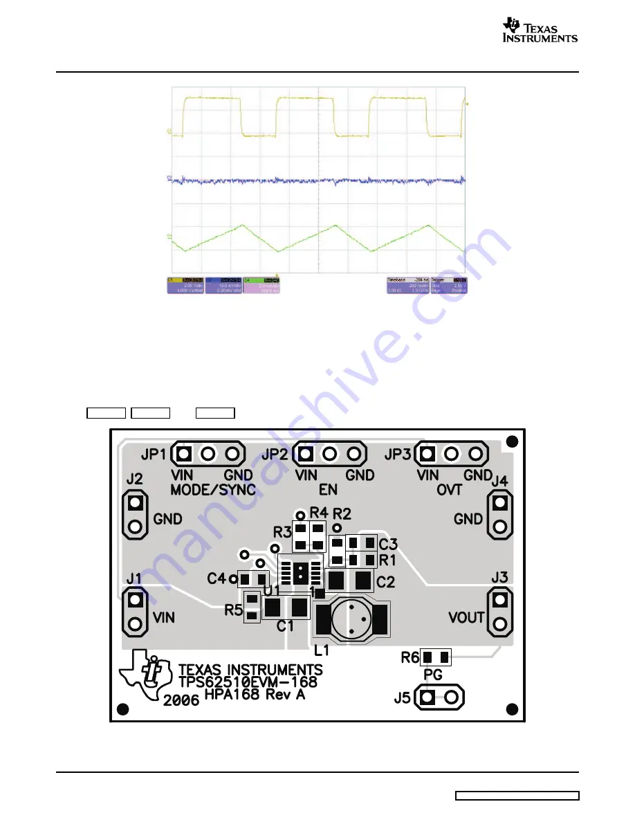
Figure 6. Output Ripple Voltage
This chapter provides the TPS62510-168 board layout and illustrations.
Figure 7
,
Figure 8
, and
Figure 9
show the board layout for the TPS63510-168 PWB.
Figure 7. Assembly Layer
6
TPS62510EVM-168
SLVU161 – May 2006
Submit Documentation Feedback


