USS READY STATE
(UUPSCTL.UPSTATE = 3)
Configure SDHSCTL0, SHDSCTL1, SDHSCTL2, SDHSCTL6,
SDHSCTL7, SDHSWINHITH, SDHSWINLOTH, and SDHSDTCSA registers
(order does not matter)
Write 1 to SDHSCTL3.TRIGEN
Write 1 to SDHSCTL4.SDHSONt
Write 1 to SDHSCTL5.SSTART bit
(If SDHSCTL0.AUTOSSDIS = 0, this step is skipped)
Data conversion is running
Starting condition:
1) USS is fully powered up including HSPLL
2) UUPSCTL.ASQEN = 0
SDHS Triger Source:
SDHSCTL0.TRGSRC= 0
Wait for the SDHS Settling Time
(If SDHSCTL0. AUTOSSDIS = 0, this step is skipped)
SDHS Functional Operation
583
SLAU367P – October 2012 – Revised April 2020
Copyright © 2012–2020, Texas Instruments Incorporated
Sigma-Delta High Speed (SDHS)
22.2.6.1.1 SDHS Configuration in Register Mode
In register mode (SDHSCTL0.TRGSRC = 0), the SDHS can be used as an stand-alone ADC converter.
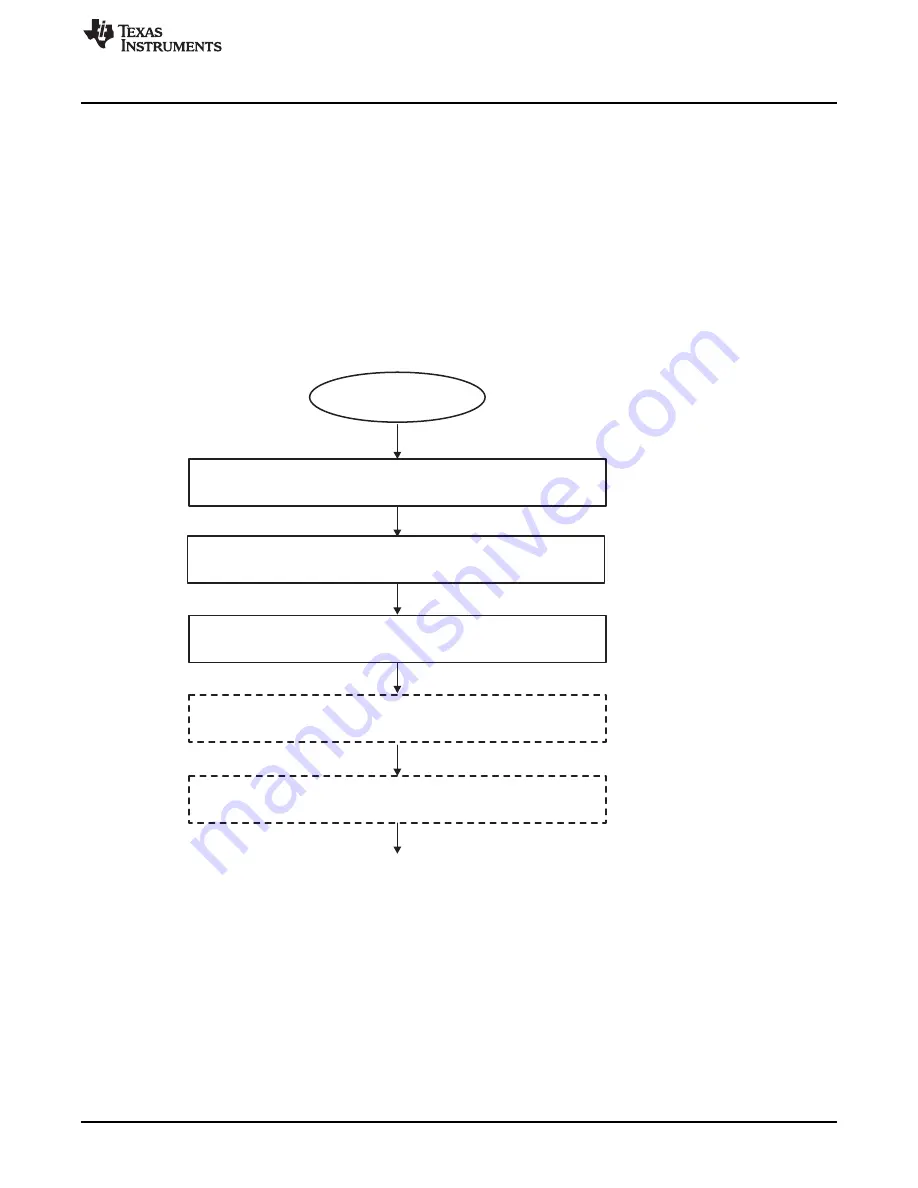
See the following sequence for the correct SDHS configuration:
1. Turn on the USS module and wait for UUPSCTL.UPSTATE = 3.
2. Configure all registers except the SDHSCTL3, SDHSCTL4, and SDHSCTL5 registers (no specific
order is required, SDHSCTL0.TRGSRC = 0).
3. Enable trigger sources: Set SDHSCTL3.TRIGEN = 1.
4. Power up the SDHS: Set SDHSCTL4.SDHSON = 1 (If SDHSCTL0.AUTOSSDIS = 1, then the
remaining steps are not required).
5. Wait for the SDHS settling time (see
).
6. Start conversion: Set SDHSCTL5.SSTART = 1.
shows this configuration sequence.
Figure 22-17. SDHS Operation in Register Mode (SDHSCTL0.TRGSRC = 0)
22.2.6.1.2 SDHS Configuration in Auto Mode
In auto mode (SDHSCTL0.TRGSRC = 1), the SDHS is fully controlled by the ASQ. See the following
sequence for the correct SDHS configuration:
1. Configure all registers except SDHSCTL3, SDHSCTL4, and SDHSCTL5 (no specific order is required,
SDHSCTL0.TRGSRC = 1).
2. Enable trigger sources: Set SDHSCTL3.TRIGEN = 1.
3. Turn on the USS module.
shows an example of USS measurement in auto mode (see
for details).


