Setting the Serial Port Mode
9-9
Serial Communication
The divide-by-32 is a result of the f
OSC
being divided by 2 (by setting
T2CON.TCLK and T2CON.RCLK) and the Timer 2 overflow being divided by
16.
To determine the RCAP2H:RCAP2L value from a given baud rate use the
equation below:
RCAP2H : RCAP2L
+
(65536
*
f
OSC
32
@
BaudRate
)
Table 9−3. Common Baud Rates Using Timer 2
Baud Rate
C/T2
RCAP2H:RCAP2L (@ 11.0592MHz f
OSC
)
57.6k
0
0FFFA
H
19.2k
0
0FFEE
H
9.6k
0
0FFDC
H
4.8k
0
0FFB8
H
2.4k
0
0FF70
H
1.2k
0
0FEE0
H
9.2.3
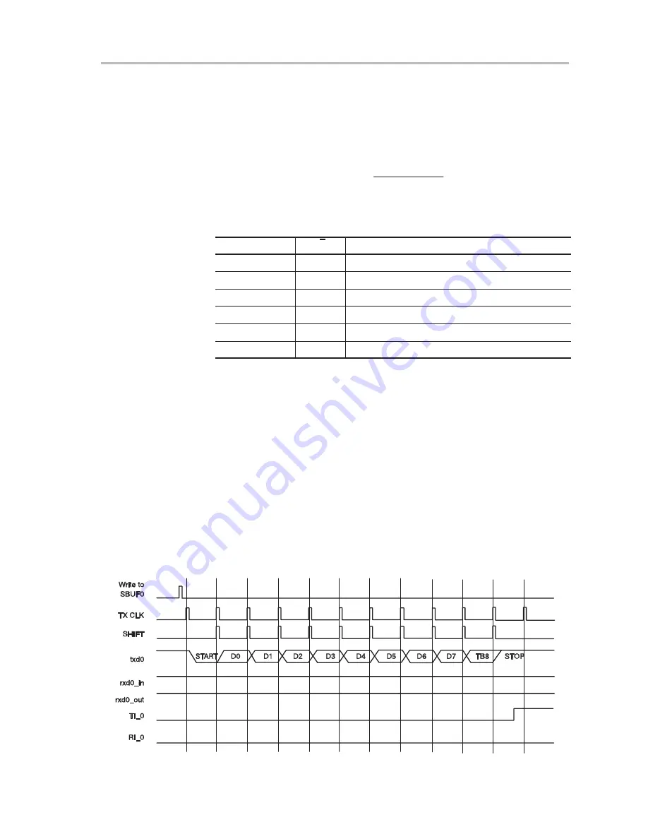
Serial Mode 2: Asynchronous Full-Duplex
In mode 2, serial data transfers are 11 bits long, full-duplex, and asynchronous.
The transfer begins with a start bit, followed by eight bits of data (LSB first),
an additional bit of data (ninth bit), then a stop bit. On transmit, the ninth data
bit is set by TB8. On receive, the ninth bit is shifted into the RB8 bit in the SCON
register and the stop bit is ignored. The baud rate is either f
OSC
/64 or f
OSC
/12.
RXD is used for receiving data, TXD is used for transmitting data, LSB first.
On transmission, SCON.TB8 is used for the ninth bit. On reception the ninth
bit goes into RB8 in the SCON register. The baud rate is selectable at f
OSC
/32
or f
OSC
/64.
Figure 9−5. Serial Port 0 Mode 2 Transmit Timing.
Содержание MSC1210
Страница 1: ... December 2002 User s Guide SBAU077 ...
Страница 149: ...Digital Filter 12 13 Analog to Digital Converter Figure 12 5 Filter Frequency Responses ...
Страница 162: ...12 26 ...
Страница 234: ...Timers 17 6 Figure 17 4 Timer Counter 1 Mode 1 Figure 17 5 Interrupt System ...
Страница 273: ...Serial Port I O 17 45 Keil Simulator Figure 17 19 Clock Control Peripheral Figure 17 20 USART0 Preipheral ...
Страница 282: ...C 4 ...


