For example, if the motor Ke is 5 mV/Hz and the application require measuring motor speed above 4 Hz, then
the user can configure FG_BEMF_THR to 20 mV. Once when the motor speed reaches 4 Hz, the device will
output FG as the BEMF voltage will be 20 mV at 4 Hz.
4.2.2 Improving Acoustic Performance
Acoustics is audible noise contributed by motor commutation and harmonic frequencies in motor drives. Stator
excitation in motor drivers can generate mechanical resonance at audible frequency ranges leading to audible
noise. Improving acoustic performance is important for applications that require quiet operation. Any distortion in
phase current can translate to audible noise. Phase current distortion can be due to dead time, PWM modulation
scheme or low MOSFET slew rate.
Step 1: Configure PWM Modulation scheme [PWM_MOD] to “Continuous Space Vector Modulation”.
Note
1. In Continuous Space vector modulation, phase current waveform shaping will be better but the
MOSFET switching losses will be higher.
2. In Discontinuous Space vector modulation, MOSFET switching losses will be lower. However, we
can expect phase current distortion for low inductance motors.
Step 2: Enable Dead time compensation [DEADTIME_COMP_EN]
For speeds above 125 Hz, decrease MCC dead time [MCC_DEAD_TIME] till the phase current distortion gets
better.
Note
Decreasing the dead time might trigger Hardware lock detection current limit fault
[HW_LOCK_ILIMIT]. If this fault gets triggered, increase the dead time.
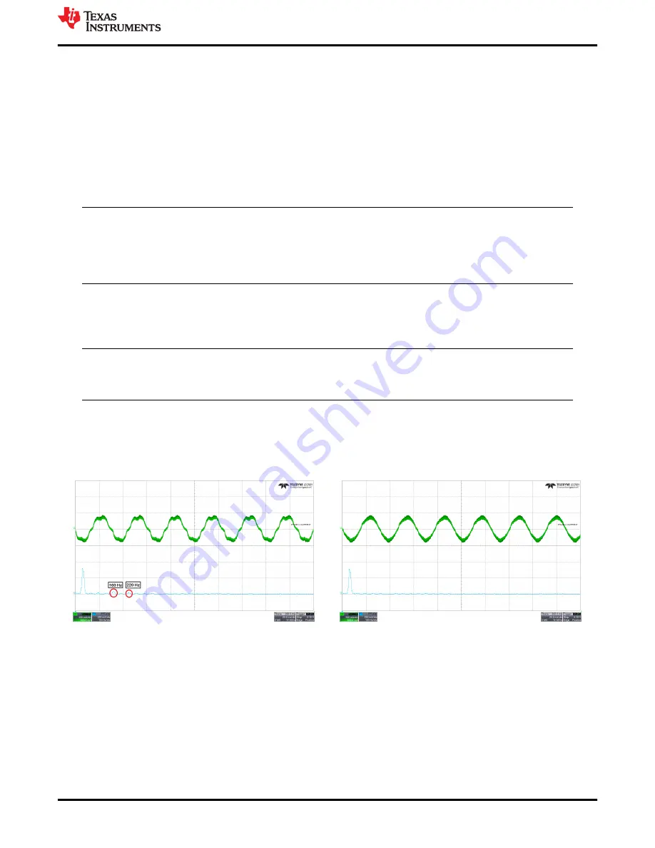
shows the phase current waveform when dead time compensation is disabled. Fundamental
frequency of phase current is 40 Hz. Fast Fourier transform (FFT) of phase current plot shows harmonics at
160 Hz and 220 Hz.
shows the phase current waveform when dead time compensation is enabled.
Phase current looks more sinusoidal and the FFT of phase current plot does not have any harmonics.
Figure 4-1. Phase current and FFT - Dead time
compensation disabled
Figure 4-2. Phase current and FFT - Dead time
compensation enabled
4.2.3 Protecting the Power supply
Protecting the power supply from drawing higher current or potential voltage overshoots is important in battery
operated applications or applications that do not have an internal overcurrent or overvoltage protection built into
the power supply.
Step 1: When the load on the motor increases, device draws higher current from the power supply. For
applications that may want to limit the current drawn from the power supply, it is recommended to Enable Bus
current limit [BUS_CURRENT_LIMIT_ENABLE] and configure the Bus current limit [BUS_CURRENT_LIMIT] to
protect the power supply from drawing higher current.
Basic Controls
SLLU335A – AUGUST 2021 – REVISED JANUARY 2022
MCF8316A Tuning Guide
13
Copyright © 2022 Texas Instruments Incorporated


