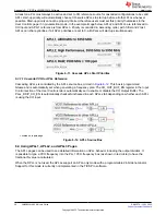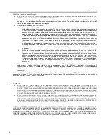
At least one PLL must always be active and set to XO reference source for cascaded configurations to be valid.
APLL start-up priority will automatically choose XO-source APLLs to start up before all other PLLs whenever
possible. Start-up priority cannot be properly inferred, therefore users must set this priority themselves in the
User Controls
page if in pin-selection mode. In the example image below, APLL2 and APLL3 are referenced to
XO input and APLL1 reference is from APLL3. Priority is controlled in ascending order, with 0 first and 2 last.
APLLs can share priorities; if all APLL priorities are set to 0, all APLLs will start up simultaneously.
Figure 6-11. Cascade APLL Start Priorities
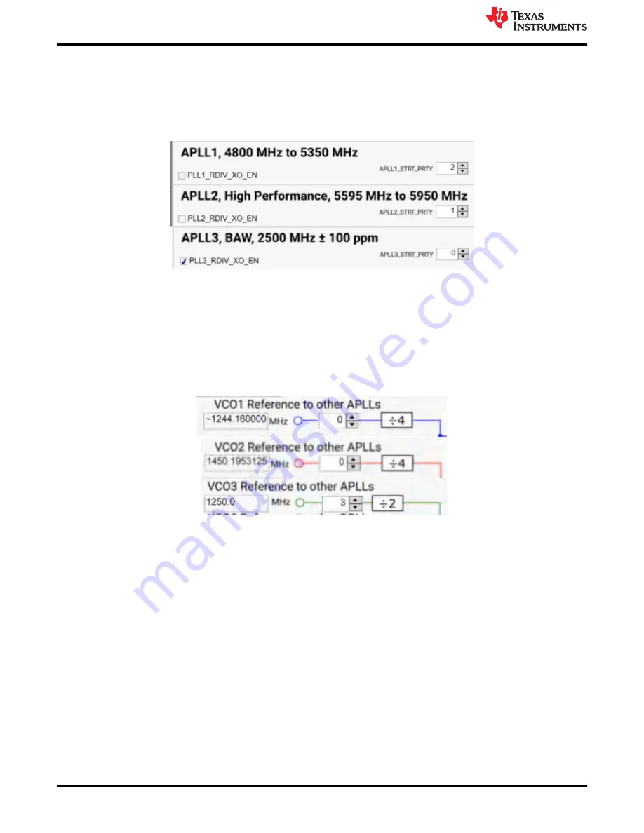
6.3.1.1 Cascade VCO to APLL Reference
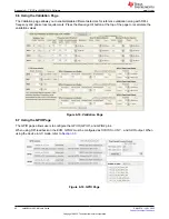
Cascading APLLs is controlled by the APLL source box, circled in
. This box is programmed
bitwise and is automatically set when generating a frequency plan. The XO_OUT_BUF_EN register in the
Input
Control
section of the
User Controls
tab is automatically set to enable or disable the XO Output Buffer. The
PLLx_RDIV_XO_EN is automatically checked/unchecked in each APLLx tab depending on whether each APLL
is using the XO input.
Located on Inputs page
Figure 6-12. APLL Source Box
6.4 Using APLL1, APLL2, and APLL3 Pages
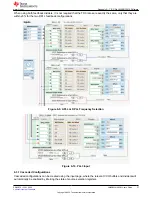
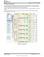
The APLL pages can be used to see detailed information on APLL behavior including the output dividers. It
is possible to type a VCO frequency into the PLL1 VCO frequency box (as shown in red circle) to have the
fractional N value re-calculated.
When the DPLL is not used, the APLLs support an APLL-only mode with a programmable 24-bit denominator.
Support for this mode is currently not implemented in the TICS Pro software.
Appendix A - TICS Pro LMK5B33414 Software
38
LMK5B33414EVM User's Guide
SNAU279 – JULY 2022
Copyright © 2022 Texas Instruments Incorporated


