Evaluation Board Layer
www.ti.com
10
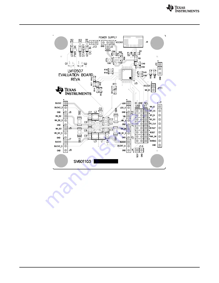
Figure 7. LM10507 Board Top Layer
LM10507 User's Guide
SNVU409 – May 2014
Submit Documentation Feedback
Copyright © 2014, Texas Instruments Incorporated
Страница 1: ...luation Kit is a self contained evaluation platform allowing access to the device outputs with software provided to test the device control functions The EVM is designed to be connected to a computer via a USB cable and can be powered from this input or may be powered from an external supply It may also be used as a stand alone board powered externally to provide the pre set default output values ...
Страница 2: ... change in the device outputs the Poll Status check box must be set From the menus there is a facility to enable direct register access should the user require this 4 Hardware Set Up Please use ESD protection when handling the evaluation boards to prevent any damage due to ESD events Connect the LM10507 Evaluation board to the USB port of a PC using the USB cable When the USB board is plugged in f...
Страница 3: ...r the state of the I O pins and the voltage measurement results The screen is updated accordingly Auto write checkbox If this box is checked any change to the registers will be written to the device immediately Otherwise the user must press Write regs button to send the update to the registers In this way the user can change values in several registers and update the changes in one communication b...
Страница 4: ...s to clipboard The log window can be cleared by pressing clear button 6 Menus Under File menu the user can save and load contents of the device registers Under Tools menu the user can open Direct Register Access dialog shown in figure 4 4 LM10507 User s Guide SNVU409 May 2014 Submit Documentation Feedback Copyright 2014 Texas Instruments Incorporated ...
Страница 5: ...e or USB controlled settings for device functions 7 1 Power Supply The evaluation board may be powered from a battery connector or from the USB interface Set jumper between J2 pin2 and TP36 to use supply from USB Maximum current available for the EVM when using the USB supply will be 500mA Table 1 Battery Connector Pins BATTERY CONNECTOR J2 Pin Function 1 Battery terminal 2 GND 8 Control A green L...
Страница 6: ...in Function 1 VIN_B1 2 VIN_B1 sense 3 GND Table 4 Connector J4 Pins Pin Function 1 BUCK1 2 BUCK1 sense 3 GND Table 5 Connector J5 Pins Pin Function 1 VIN_B2 2 VIN_B2 sense 3 GND Table 6 Connector J6 Pins Pin Function 1 BUCK2 2 BUCK2 sense 3 GND Table 7 Connector J7 Pins Pin Function 1 VIN_B3 2 VIN_B3 sense 3 GND Table 8 Connector J8 Pins Pin Function 1 BUCK3 2 BUCK3 sense 6 LM10507 User s Guide SN...
Страница 7: ... Function 3 GND Table 9 Connector J11 Pins Pin Function 1 VIN 2 VIN sense 3 GND Table 10 Connector J12 Pins Pin Function 1 LDO 2 LDO sense 3 GND 7 SNVU409 May 2014 LM10507 User s Guide Submit Documentation Feedback Copyright 2014 Texas Instruments Incorporated ...
Страница 8: ...LD3 PWR_OK 1 2 3 60V Q1 2N7002ET1G PWR_OK 1 2 J13 VCC3 8 1 TP36 POWER SUPPLY TEST 22μF C9 1 2 3 J11 1 2 3 J12 1 2 3 J3 TSW 103 07 G S 1 2 3 J4 TSW 103 07 G S 1 2 3 J6 TSW 103 07 G S 1 2 3 J7 TSW 103 07 G S 1 2 3 J8 TSW 103 07 G S 1 2 J14 DNF 5 4 1 2 3 6 7 8 9 10 J1 2 1 3 JP2 2 1 3 JP3 2 1 3 JP4 2 1 3 JP5 2 1 3 JP6 2 1 3 JP7 2 1 3 JP8 2 1 3 JP9 Assembly Note ZZ5 Jumpers SH J2 to SH J09 and SH J11 i...
Страница 9: ...2 2 16 P2 1 17 P2 0 18 P1 7 19 P1 6 20 P1 5 21 P1 4 22 P1 3 23 P1 2 24 P1 1 25 P1 0 26 P0 7 27 P0 6 28 P0 5 29 P0 4 30 P0 3 31 P0 2 32 U5 C8051F320 GQ 30 ohm FB1 2 3 4 1 5 J9 1 2 JP11 RESET_USB ENABLE_USB VCC LDO 10μF C59 200k R55 100k R56 10μF C60 4 7μF C45 0 1μF C46 0 1μF C50 4 7μF C49 10 0k R62 1 50k R34 LDO_S B2_S B3_S B1_S VBATT_S 10 0k R11 10 0k R13 10 0k R16 18 2k R18 10 0k R19 www ti com S...
Страница 10: ...uation Board Layer www ti com 10 Evaluation Board Layer Figure 7 LM10507 Board Top Layer 10 LM10507 User s Guide SNVU409 May 2014 Submit Documentation Feedback Copyright 2014 Texas Instruments Incorporated ...
Страница 11: ...www ti com Evaluation Board Layer Figure 8 LM10507 Board Inner Layer 2 11 SNVU409 May 2014 LM10507 User s Guide Submit Documentation Feedback Copyright 2014 Texas Instruments Incorporated ...
Страница 12: ...Evaluation Board Layer www ti com Figure 9 LM10507 Board Inner Layer 3 12 LM10507 User s Guide SNVU409 May 2014 Submit Documentation Feedback Copyright 2014 Texas Instruments Incorporated ...
Страница 13: ...www ti com Evaluation Board Layer Figure 10 LM10507 Board Inner Layer 4 13 SNVU409 May 2014 LM10507 User s Guide Submit Documentation Feedback Copyright 2014 Texas Instruments Incorporated ...
Страница 14: ...ring the warranty period to the address designated by TI and that are determined by TI not to conform to such warranty If TI elects to repair or replace such EVM TI shall have a reasonable time to repair such EVM or provide replacements Repaired EVMs shall be warranted for the remainder of the original warranty period Replaced EVMs shall be warranted for a new full ninety 90 day warranty period 3 ...
Страница 15: ... by Industry Canada to operate with the antenna types listed in the user guide with the maximum permissible gain and required antenna impedance for each antenna type indicated Antenna types not included in this list having a gain greater than the maximum gain indicated for that type are strictly prohibited for use with this device Concernant les EVMs avec antennes détachables Conformément à la rég...
Страница 16: ... connecting any load to the EVM output If there is uncertainty as to the load specification please contact a TI field representative During normal operation even with the inputs and outputs kept within the specified allowable ranges some circuit components may have elevated case temperatures These components include but are not limited to linear regulators switching transistors pass transistors cu...
Страница 17: ...F REMOVAL OR REINSTALLATION ANCILLARY COSTS TO THE PROCUREMENT OF SUBSTITUTE GOODS OR SERVICES RETESTING OUTSIDE COMPUTER TIME LABOR COSTS LOSS OF GOODWILL LOSS OF PROFITS LOSS OF SAVINGS LOSS OF USE LOSS OF DATA OR BUSINESS INTERRUPTION NO CLAIM SUIT OR ACTION SHALL BE BROUGHT AGAINST TI MORE THAN ONE YEAR AFTER THE RELATED CAUSE OF ACTION HAS OCCURRED 8 2 Specific Limitations IN NO EVENT SHALL T...
Страница 18: ...esponsible for compliance with all legal regulatory and safety related requirements concerning its products and any use of TI components in its applications notwithstanding any applications related information or support that may be provided by TI Buyer represents and agrees that it has all the necessary expertise to create and implement safeguards which anticipate dangerous consequences of failur...