Using the Evaluation Software
5.1
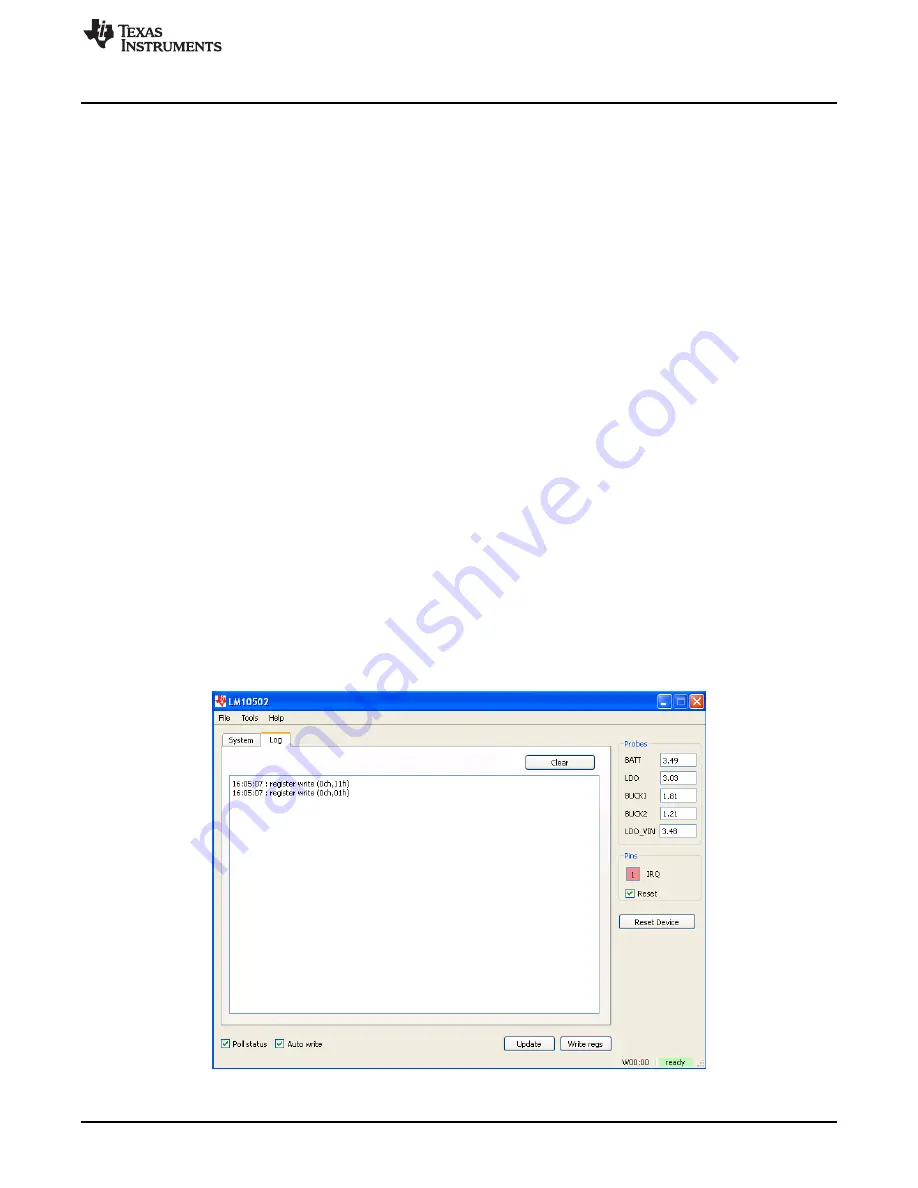
Main Screen (Figures 2 & 3)
Right and lower part of screen is visible as the background for both tab screens. Common functions can
be controlled here.
5.2
Right Part of Screen
The
Probes
frame contains results of voltage measurements. Values can be read the moment when the
device becomes active.
The
Pins
frame shows the status of the
IRQ
and
Reset
pins.
Pressing the
RESET_DEVICE
button causes a 50-ms negative pulse in reset pin.
5.3
Lower Part of Screen
This part of the screen contains following check-boxes and buttons:
Poll status
checkbox:
Allows continuous reading of the evaluation chip status register, state of I/O pins, and voltage
measurement results
Auto write
checkbox:
If this box is checked, any change to registers will be written to the device immediately. Otherwise, user
must press
Write regs
button to update registers. This way, user can change values in several registers
and update changes simultaneously.
Update
button:
Reads content of every register and updates screen accordingly.
Write regs
button:
If
Auto write
checkbox is disabled, user can press this button to update content of every register.
There is a status bar at the bottom of the screen. It shows if connection to evaluation board is established,
and information about the last register write/read operation. Register information is given in the format:
‘’R/WXX:YY’’, where first letter indicates operation (read or write), XX is register address and YY is data.
Figure 3. Log Tab
3
SNVU277 – January 2014
Copyright © 2014, Texas Instruments Incorporated


