Texas Instruments IWR6843L EVM Скачать руководство пользователя страница 15

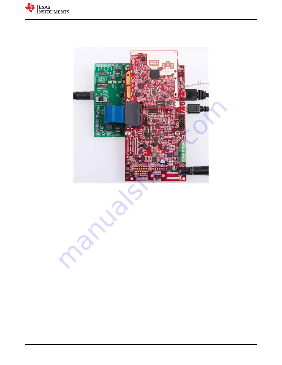
5.15 Raw ADC Data Capture Using MMWAVEICBOOST and DCA1000 EVMs

This mode enables raw data capture using the DCA1000 EVM via MMWAVEICBOOST. MMWAVEICBOOST 
supports higher current and camera mount options.

Figure 5-11. mmWAVEICBOOST With DCA1000 Mode

5.16 Muxing Scheme

The IWR6843LEVM UART RX/TX can be routed to the Samtec 60-pin connector, USB to UART (SICP2105) 
using S1.5 switch.

6 Software, Development Tools, and Example Code

To enable quick development of end applications on the C67x DSP and Arm Cortex R4F core in the IWR6843, TI 
provides a software development kit (SDK) that includes demo codes, software drivers, emulation packages for 
debug, and more. These can be found at 

mmwave-sdk

.

You can also visit the TI resource explorer for the mmWave product from 

here

. You will find Toolbox for mmWave 

Sensors, experiments, labs, and various demo examples.

7 TI E2E Community

Search the forums at 

e2e.ti.com

. If you cannot find your answer, post your question to the community.

8 References

• Texas Instruments: 

DCA1000EVM Data Capture Card User’s Guide

• Texas Instruments: 

MMWAVEICBOOST & 60GHz EVM User’s Guide

Hardware Setup for IWR6843ISK and IWR6843ISK-ODS | TI.com Video

Hardware Setup for MMWAVEICBOOST and antenna module | TI.com Video

mmwave-sdk

USB to UART Drivers for the CP2105

www.ti.com

Hardware Details

SWRU585 – NOVEMBER 2021

Submit Document Feedback

IWR6843L EVM

15

Copyright © 2021 Texas Instruments Incorporated

Содержание IWR6843L EVM

Страница 1: ...M Antenna 6 4 1 Transmitter and Receiver Virtual Array 7 5 Hardware Details 8 5 1 Switch Settings 8 5 2 LEDs 9 5 3 Connectors 9 5 4 USB Connector 9 5 5 DCA1000 HD Connector 10 5 6 MMWAVEICBOOST HD Connector 10 5 7 CANFD Connector 10 5 8 I2C Connections 11 5 9 EEPROM 11 5 10 Default I2C Address 11 5 11 Modular Mode 11 5 12 Flashing the Board 13 5 13 DCA1000EVM Mode 13 5 14 MMWAVEICBOOST Mode 14 5 1...

Страница 2: ...iver USB powered standalone mode of operation 1 2 Kit Contents The following items are included in the IWR6843LEVM IWR6843LEVM Evaluation board Micro USB 1 3 mmWave Out of Box Demo TI provides sample demo codes to easily get started with the IWR6843LEVM evaluation module EVM and to experience the functionality of the IWR6843 radar sensor For details on getting started with these demos see www ti c...

Страница 3: ...IWR6843 operates at a 4 GHz bandwidth from 60 to 64 GHz The IWR6843LEVM has an antenna gain of 5 6 dBi across different antenna pairs Figure 2 1 IWR6843LEVM Top View Figure 2 2 IWR6843LEVM Bottom View www ti com Hardware SWRU585 NOVEMBER 2021 Submit Document Feedback IWR6843L EVM 3 Copyright 2021 Texas Instruments Incorporated ...

Страница 4: ... 3 Salient features of EVM top side Figure 2 4 Salient features of EVM bottom side Hardware www ti com 4 IWR6843L EVM SWRU585 NOVEMBER 2021 Submit Document Feedback Copyright 2021 Texas Instruments Incorporated ...

Страница 5: ...N CONNECTOR 5 V GPIO 2 0 DP 7 0 LVDS SPI JTAG RS232 RESET MISC RX TX 1 7 V VPP VOUT_PA VOUT_SYNTH VOUT_PLL VBGAP 1 8 V 1 0V 1 2 V 1 8 V 1 0 V OPTIONAL XTAL 40 MHz 5V_IN Max 5 5 V I2C 3 3 V 3 3 V 1 8 V 1 2V USB TO UART SIC2105 Mux A A UART RS232TX RX B SOP2 SOP2 Mux SOP Switch B MSS_logger DCA1000 60 PIN CONNECTOR Reset Button DCDC Buck Converter TPS628502HQDR LRQ1 DCDC Buck Converter TPS6285020MQ ...

Страница 6: ...r performance would be intact To avoid oxidation the PCB should be stored in an ESD cover and kept at a controlled room temperature with low humidity conditions All ESD precautions must be taken while using and handling the EVM 3 2 Higher Power Demanding Applications For higher power applications which single USB port cannot supply for example simultaneous 3 Tx operation MMWAVEICBOOST board could ...

Страница 7: ...re 4 2 Virtual Antenna Array Figure 4 3 shows the antenna radiation pattern with regard to azimuth Figure 4 4 shows the antenna radiation pattern with regard to elevation for TX1 TX2 and TX3 Both show the radiation pattern for TX1 TX2 and TX3 and RX1 RX2 RX3 and RX4 together All of the measurements were done with a Tx and Rx combination together Thus for the 6dB beam width you must see a 12db Tx 6...

Страница 8: ...ns of the switches on the IWR6843LEVM Figure 5 1 Part Designators and Positions of the Switches on the IWR6843LEVM Table 5 1 Switches Buttons and Muxes Reference Designator Switch On Switch Off S1 1 SOP2 pulled up SOP2 pulled down S1 2 SOP1 pulled up SOP1 pulled down S1 3 SOP0 pulled up SOP0 pulled down S1 4 Muxes to CAN connector J3 J4 Muxes to serial peripheral interface SPI on 60 pin connector ...

Страница 9: ...connector is not required Note After the 5 V power supply is provided to the EVM TI recommends pressing the NRST switch one time to ensure a reliable boot up state Note All digital IO pins of the device except NERROR IN NERROR_OUT and WARM_RESET are non failsafe hence care needs to be taken that they are not driven externally without the VIO supply being present to the device 5 4 USB Connector The...

Страница 10: ... I2C NRST NERR and SOPs and JTAG debug signals to the MMWAVEICBOOST The Trace and DMM interface lines are also available through this connector not connected by default Figure 5 4 MMWAVEICBOOST HD Connector 5 7 CANFD Connector The CAN connector provides access to the two CAN_FD interfaces CAN_L and CAN_H signals from the onboard CAND FD transceivers These signals can be directly wired to the CAN b...

Страница 11: ...OST 5 10 Default I2C Address Table 5 4 provides the list of I2C devices and its address Table 5 4 List of I2C Device and Addresses Sensor Type Designator Part Number Slave Address Temperature sensor U3 TMP112AQDRLRQ1 100 1011 EEPROM J11 CAT24C08W1 GT3 101 00XX 1 Current sensor 1 U6 INA226AIDGST 100 0000 Current sensor 2 U7 INA226AIDGST 100 0101 Current sensor 3 U8 INA226AIDGST 100 0001 Current sen...

Страница 12: ...rd COM port is the data port The S1 switch setting for functional and flashing mode is shown in Table 5 5 Table 5 5 S1 Swtch Setting for Functional and Flashing Mode S1 1 S1 2 S1 3 S1 4 S1 5 S1 6 Flashing On Off On On Off Functional Off Off On On Off Hardware Details www ti com 12 IWR6843L EVM SWRU585 NOVEMBER 2021 Submit Document Feedback Copyright 2021 Texas Instruments Incorporated ...

Страница 13: ...ons please refer training videos from training ti com link provided below Hardware Setup for IWR6843ISK and IWR6843ISK ODS TI com Video Hardware Setup for MMWAVEICBOOST and antenna module TI com Video 5 13 DCA1000EVM Mode The setup for raw data capture using DCA1000EVM is shown in Figure 5 9 Figure 5 9 DCA1000EVM Mode S1 switch settings for this mode is shown in Table 5 6 Table 5 6 S1 Configuratio...

Страница 14: ...mera mount option CAN Launchpad connector and so forth Note In MMWAVEICBOOST mode the IWR6843LEVM is mounted on the MMWAVEICBOOST and the SOP mode is set by the MMWAVEICBOOST More on the mmWAVEICBOOST setup and features it provides can be found in the MMWAVEICBOOST section of MMWAVEICBOOST EVM userguide Figure 5 10 MMWAVEICBOOST Mode Hardware Details www ti com 14 IWR6843L EVM SWRU585 NOVEMBER 202...

Страница 15: ...are drivers emulation packages for debug and more These can be found at mmwave sdk You can also visit the TI resource explorer for the mmWave product from here You will find Toolbox for mmWave Sensors experiments labs and various demo examples 7 TI E2E Community Search the forums at e2e ti com If you cannot find your answer post your question to the community 8 References Texas Instruments DCA1000...

Страница 16: ...o change without notice TI grants you permission to use these resources only for development of an application that uses the TI products described in the resource Other reproduction and display of these resources is prohibited No license is granted to any other TI intellectual property right or to any third party intellectual property right TI disclaims responsibility for and you will fully indemn...

Отзывы: